A question on SN74ALS138N

Thread Starter

harisudharsan

Joined May 6, 2014
16
Hi Team,

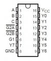
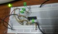
I am trying to test my basic understanding over the decoder chip by doing a simple circuit practically. I connected 4 LEDs on the output lines (Y 0,1,2,7) and made all the inputs to High.

I was expecting to see the Y 0,1,2 LEDs to glow and Y7 LED must not glow (as per the table provided in the datasheet of this chip. But to my surprise I found all the LEDs are glowing.

Later I brought the A,B,C to low. Still all the LEDs were glowing. Am I missing some thing some where ?? I double checked, that there is no show circuit. I ensured to keep the G1 high while checking this.

Attached is the circuit. .

With Regards,
S.Sudharsan
 

Attachments

Thread Starter

harisudharsan

Joined May 6, 2014
16
If it is not connected to any thing is it not already logically low ??

Low means 0 volts right ?? So if i am not connecting any thing to it, is it not already low ??

Regards,
S.Sudharsan
 

djsfantasi

Joined Apr 11, 2010
9,237
If it is not connected to any thing is it not already logically low ??

Low means 0 volts right ?? So if i am not connecting any thing to it, is it not already low ??
As a matter of fact, if it is not connected to anything, it is undefined, particularly in CMOS ICs. Older TTL actually used to see an unconnected input as a high signal!
 

MrChips

Joined Oct 2, 2009
34,807
Sudharsan, welcome to the world of electronics.
There is so much to learn that they don't tell you in the classroom or in a textbook.
Hands-on experience makes a world of difference.
 

AnalogKid

Joined Aug 1, 2013
12,126
Also, it looks like the upper left LED is tied directly across the power pins with no current limiting resistor. This could be why it is so bright. Unless they are special LEDs with current limiting built in, all LEDs need external current limiting, such as a resistor. Without them, the chip will not last long.

ak
 

Thread Starter

harisudharsan

Joined May 6, 2014
16
Thanks Analogkid !!!

That is a very useful info. I have seen people connecting resistors & capasitors in the circuit. But i am not sure why they do and more importantly how they calculate the value of those components to be used. I was think what those components do in a digital circuit as these circuits works by truth table.

So your reply makes sence.

Can you help me how the value of those components has to be calculated ?

Regards,
S.Sudharsan
 

MrChips

Joined Oct 2, 2009
34,807
The calculations will depend on every specific situation and components used.
You have to become familiar with the basic principles such as Ohm's Law and the characteristics and variability of components.

Consider an LED with a forward voltage of 2.5V and operating current of 5mA. (These parameters will be different for a different LED).

A TTL gate powered from 5V will have an output of about 4V. (The output voltage will be different for a different family of devices).

A resistor in series has to drop the difference in voltage, i.e. 4 - 2.5V = 1.5V

Applying Ohm's Law, I = V/R

The value of the series resistance R = V/I = 1.5V/5mA = 300Ω

Use 270Ω or 330Ω since these are standard values. 270Ω will make the LED slightly brighter.

(See, there is a reason they teach Ohm's Law in school.)
 

Thread Starter

harisudharsan

Joined May 6, 2014
16
Thanks for this wonderful explanation MrChips..

I just now got from good google what is forward voltage means.

Now, In my case I used that LED (in series) with the circuit like a resistance. Actually the batter i used is a 9V battery. WhenI checked, it was giving 7 v currents (due to its age). But I found the operating voltage of the chip is 4.5-5.5 v.

So I connected this LED in series to limit the current flowing to the circuit. Which looks like a wrong thing.

But I have a question now. Lets say, I have a chip which has 6v as its operating voltage and I have the right powersupply to feed it. Now I want to add a LED to the project which has to work like a power indicator (which remains on when the circuit is closed).

Now, if i limit the current flowing to the LED using a resistance then subsequently will not it affects the voltage flowing to the CMOS chip ??

Regards,
S.Sudharsan
 

MrChips

Joined Oct 2, 2009
34,807
Do one thing at a time. Don't confuse the issue.

Say you have a 9V power supply and you want a power indicator.
Put a resistor in series with an LED across the 9V power supply.

Voltage drop across the resistor is 9V-2.5V = 6.5V
Resistor required for 5mA LED is R = V/I = 6.5V/5mA = 1.3kΩ

Choose nearest value, i.e. 1.5kΩ

Your 74LSxx chip requires 5V +/- 0.5V

You need a 5V voltage regulator to bring the 9V supply down to 5V.
Look for the LM7805 or similar 3-terminal regulator.
(There are hundreds of other 5V regulators with different part numbers, too long to list here, which would also work for your situation.)
 
Top