Facebook
 Google
 GitHub
 Linkedin
PackratKing
- Joined Jul 13, 2008
- 847
Brief mention / attention was given on pg. 1 regarding the condition of the fields, armature, commutator / brush integrity. Will the fields - armature and comm. pass a growler and Hi-pot test ??
If when the motor is run open - unladen by the scooter, do the brushes spark ?? very little is allowable. Are the insulations between the commutator bars undercut and free of copper detritus from sanding between them ?? do thge brush springs have equal tension, and not show signs of blueing or scorching ------are they free in the holders, or we dealing with wilted plastic here.
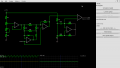
If not, the fanciest control circuit you can imagine, is going to get you a grand total of nowhere.
If when the motor is run open - unladen by the scooter, do the brushes spark ?? very little is allowable. Are the insulations between the commutator bars undercut and free of copper detritus from sanding between them ?? do thge brush springs have equal tension, and not show signs of blueing or scorching ------are they free in the holders, or we dealing with wilted plastic here.
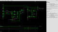
If not, the fanciest control circuit you can imagine, is going to get you a grand total of nowhere.
Last edited: