A Mobility Scooter Motor Controller issue(s)!!

Thread Starter

iONic

Joined Nov 16, 2007
1,662
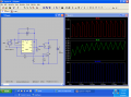
I'm really trying to understand why the first circuit, in the above post, is not working.
Some have said that 555's are not so good at PWM for higher current devices or for driving
high power MOSFET's, not sure which. But I'd like to know what the reasoning behind this are.

Are some of you unwilling to offer assistance because the device I am working with is a mobility scooter? Bottom line, if I can't fix it, it will be too expensive to repair it, it would be more than the scooter is really worth!
 

shortbus

Joined Sep 30, 2009
10,045
I've given you a couple of links to PWM circuits. But instead of using one of them you want to use part of your design and part of another design.

The timer part of your design is not really compatible with the other circuits. Mixing parts of two circuits does not always work out. I did not figure the frequency of your 555 timer design(section 1), but it should be somewhere between 40kHz and 50kHz for the PWM of a motor to get the most torque from the motor.

Also gave a link to other designs of PWM circuits and how PWM works. YOU have to do a little research of your own to understand what the circuit needs. If you help yourself more people will help you. NOT trying to be mean but this forum is the most helpful of any I've found. :)
 

Thread Starter

iONic

Joined Nov 16, 2007
1,662
O.K.
I will build the following circuit and give it a shot. Don't know what the value of D1 is or should be for my circuit. The parts list Parts List did not say.

I altered the circuit, adding the .o1uF cap to ground from pin 5 and tied pin 4 to pin 8 (LM555) as these are generally standard. Correct me if I'm wrong.

 
Last edited:

Kermit2

Joined Feb 5, 2010
4,162
I'm still of the firm belief that there is an OPEN somewhere. It was intermittant before but has become fully open. You say you have checked for bad connections, however, I have discovered in 25+ years of troubleshooting that such confidence in having checked everything is seldom correct. I've been wrong so many times when I think I have covered 'everything', that I no longer trust anyone who says they have checked 'everything'. Look somewhere you KNOW it couldn't be, and you are liable to find a simple reason for the original problem. Having gone so far into this alternate scheme, feel free to ignore my advice. I don't expect to hear any thanks from anyone, and I'm deaf to cursing as well.

:)
 

Thread Starter

iONic

Joined Nov 16, 2007
1,662
I'm still of the firm belief that there is an OPEN somewhere. It was intermittent before but has become fully open. You say you have checked for bad connections, however, I have discovered in 25+ years of troubleshooting that such confidence in having checked everything is seldom correct. I've been wrong so many times when I think I have covered 'everything', that I no longer trust anyone who says they have checked 'everything'. Look somewhere you KNOW it couldn't be, and you are liable to find a simple reason for the original problem. Having gone so far into this alternate scheme, feel free to ignore my advice. I don't expect to hear any thanks from anyone, and I'm deaf to cursing as well.

:)
We'll, since I did not find the "problem" but really only narrowed it down to the
Motor controller, you are right and I would not bet a whole lot of anything that it is not some sort of "open/short" situation.
 

Thread Starter

iONic

Joined Nov 16, 2007
1,662
Thought I had 1 or 2 LM393's, but I can't find them.
I do, however have a slew of others.

Need a suitable replacement from the list below.

LM301AN
TL082CP
LM386N
LM358P

LM311N

Above circuit redrawn with LM311 Comparator
 
Last edited:

tom66

Joined May 9, 2009
2,595
One of the problems you will have with that circuit is that the fet's gate will have to be charged by the 2.2k resistor. The gate capacitance might be a few nanofarads which doesn't sound like much, but at high speeds a substantial amount of time will be spent charging, and discharging, that gate meaning that it often is in the linear region, dissipating a lot of heat. I'd recommend using a proper driver circuit, even a basic push-pull amplifier should do, but ideally a dedicated MOSFET driver. These drivers are capable of 1.5A+ charging and discharging spikes.
 

ronv

Joined Nov 12, 2008
3,770
If you use something like an IRFZ40 FET and MRB1545 diode you can drive it easily with the 555 on 12 volts.
 

Thread Starter

iONic

Joined Nov 16, 2007
1,662
One of the problems you will have with that circuit is that the fet's gate will have to be charged by the 2.2k resistor. The gate capacitance might be a few nanofarads which doesn't sound like much, but at high speeds a substantial amount of time will be spent charging, and discharging, that gate meaning that it often is in the linear region, dissipating a lot of heat. I'd recommend using a proper driver circuit, even a basic push-pull amplifier should do, but ideally a dedicated MOSFET driver. These drivers are capable of 1.5A+ charging and discharging spikes.
Could you suggest one?
 

ronv

Joined Nov 12, 2008
3,770
Don't know why I was lazy last night. Here is a circuit that should work fine, but I to am beginning to think the motor is intermittent.
Do you know how much current your motor draws for sure?
 

Attachments

Thread Starter

iONic

Joined Nov 16, 2007
1,662
If you use something like an IRFZ40 FET and MRB1545 diode you can drive it easily with the 555 on 12 volts.
Most others have suggested that the scenario you offer will not work.

Don't know why I was lazy last night. Here is a circuit that should work fine, but I to am beginning to think the motor is intermittent. Do you know how much current your motor draws for sure?

All I can really say is that the motor is rated at 24V, 15A @ 3500 RPM's. I don't believe the motor is intermittent, but will doo a bit of testing with the leads that power it.
 
Last edited:

Thread Starter

iONic

Joined Nov 16, 2007
1,662
Well, my friend hand finished programming and building a motor controller for my scooter. He had it running with display panel showing the Vbatt, Ibatt, PWM %. Tried it with the scooter and it only went full speed on none. I believe it did go reverse as well but also full speed or none. This was despite the PWM signal showing 0 - 100%. Then he was working on it and did some things and started to blow MOSFETS.

Sorry, cant give you a schematic of what he had going. Aside from the uC, the circuit needs to redrawn and rebuilt.


I am eyeballing a Motor driver from Pololu, Pololu High-Power Motor Driver 24v23 CS
I figured with his uC we could make this thing work. It is a 23A Motor Driver, requiring no heat-sinks, I assume because the MOSFET's are rated at more than 100A.
IRLR7843 DataSheet

...And since my scooter moter is rated at 15A I probably wont even see half of the 23A.

What do you all think? Is it a workable solution? Will this driver be compatible and adequate?
 

THE_RB

Joined Feb 11, 2008
5,438
Pololu make some nice stuff but to me that still looks a little small for a vehicle motor driver.

Check out "TheRobotStore" they have some larger drivers for PWM DC motor control and if I remember right they have overcurrent protection etc which you need in scooter vehicles, the moment you try to get up a small step or ramp the motor can be subject to very high overload currents.
 

Thread Starter

iONic

Joined Nov 16, 2007
1,662
Pololu make some nice stuff but to me that still looks a little small for a vehicle motor driver.

Check out "TheRobotStore" they have some larger drivers for PWM DC motor control and if I remember right they have overcurrent protection etc which you need in scooter vehicles, the moment you try to get up a small step or ramp the motor can be subject to very high overload currents.

Perhaps I have the wrong site, therobotstore.com, cant seem to find anything remotely related to motor drivers.
The module has the ACS714 Current sense IC, for over current protection. The pic will have to be programmed to work with this IC.
 
Last edited:

Thread Starter

iONic

Joined Nov 16, 2007
1,662
Thanks RB. I ordered the driver board I mentioned in post #33. The board does include a current sense chip so I take it that the uC can use that output to trigger current protection.
 

THE_RB

Joined Feb 11, 2008
5,438
Yeah that Pololu one looks like good value for money. You can tie the current feedback voltage in your micro firmware to reduce PWM as current nears the maximum.

That will work similar to many of the heavy duty drivers they use in the battlebots etc as you don't want to kill the motor power when the user hits a tiny step, just avoid driver and battery damage and keep the power onto the motor for the half second it takes to jump up the step.

Please post how the Pololu board goes when it's installed. :)
 

Thread Starter

iONic

Joined Nov 16, 2007
1,662
Yeah that Pololu one looks like good value for money. You can tie the current feedback voltage in your micro firmware to reduce PWM as current nears the maximum.

That will work similar to many of the heavy duty drivers they use in the battlebots etc as you don't want to kill the motor power when the user hits a tiny step, just avoid driver and battery damage and keep the power onto the motor for the half second it takes to jump up the step.

Please post how the Pololu board goes when it's installed. :)
Thanks for the added info, RB, it will be useful. I just received the board today and was surprised that the MOSTFET IC's were not even 220 but 252 pkg. They are an Infineon IC, IPD036N04L and have a maximum continous drain current of 90A. It's hard to believe.
 
Top