A little help using this arduino AC current sensor / current transformer

Thread Starter

zirconx

Joined Mar 10, 2010
171
Yes, the sensor I linked and had a photo of in my first post. The voltages I am seeing don't match up with your calculations. Maybe the burden resistor on the board is different then what was listed in the specs. The RMS voltage on my scope matched what I was seeing on my DMM.

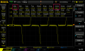
Although one odd thing I noticed is some of my test-load devices gave me weird readings. My heatgun drew 8A on low, but the sensor showed less than 1v. When I switched the heat gun to high it draws 11A, then sensor was showing 3v or something. So that's weird right? The waveform on the oscilloscope looked odd too, less "spikes", which I think would lead to a lower RMS voltage.
 

MisterBill2

Joined Jan 23, 2018
18,168
I suggest connecting the current sensor to a transistor, base and emitter, and seeing how much it turns the transistor on.
It seems that the higher loads are bringing the sensor into the saturation region, where the output no longer is proportional to the current by a constant proportion. That is as expected and true of most sensors of this kind.
 

Thread Starter

zirconx

Joined Mar 10, 2010
171
I suggest connecting the current sensor to a transistor, base and emitter, and seeing how much it turns the transistor on.
It seems that the higher loads are bringing the sensor into the saturation region, where the output no longer is proportional to the current by a constant proportion. That is as expected and true of most sensors of this kind.
Ok. I should use a full wave bridge rectifier, yes? That will provide more power through the transistor?
 

MisterBill2

Joined Jan 23, 2018
18,168
Ok. I should use a full wave bridge rectifier, yes? That will provide more power through the transistor?
a full wave bridge will also put at least two diode voltage drops in series with the voltage to the base, and at 0.7 volts each will certainly prevent any operation. So I suggest not doing that.
 

MikeA

Joined Jan 20, 2013
362
Yes, the sensor I linked and had a photo of in my first post. The voltages I am seeing don't match up with your calculations.
The fact that you don't get double the value when doing 2 turns tells me something is wrong.

I have a bunch of those sensors current clamp/transformer (like more than a dozen) and they seem to be pretty linear at least up to 15A. I didn't test higher.

Maybe the burden resistor on the board is different then what was listed in the specs. The RMS voltage on my scope matched what I was seeing on my DMM.
Does the burden resistor have something printed on it? Worse case you can just measure it. Then substitute the ohms into my calculation above.

The waveform on the oscilloscope looked odd too, less "spikes", which I think would lead to a lower RMS voltage.
The heatgun is purely resistive. Your DMM will give you the most accurate AC RMS reading with a purely resistive load. You should use the heatgun when trying to figure this out.
 

MaxHeadRoom

Joined Jul 18, 2013
28,617
My goal is only to know if the sump pump is on, not to measure how much current is flowing.
If you don't need to measure a value, then it is very simple with the non-invasive Honeywell version already quoted, or there are probably cheap oriental versions also.
These just switch on any level.
Max.
 

MisterBill2

Joined Jan 23, 2018
18,168
The blower on some heat guns is a universal brushed motor, and possibly a quite noisy one at that. Not resistive at all. But one of my heat guns does have an induction motor. So there are both kinds.
 

Thread Starter

zirconx

Joined Mar 10, 2010
171

Attachments

Reloadron

Joined Jan 15, 2015
7,501
First and before I forget your meter like most digital volt meters should be showing you the RMS voltage. Be it average or true RMS responding as long as it is a relatively well shaped sine wave what you see is what you have, an RMS voltage. The CT outputs a RMS current. Since your pump motor is an inductive load there is a little more to calculating the actual current but really it matters not for your intended application. With that in mind...

My read on what you have makes it likely a ZMCT103C Current Transformer. That or similar. The CT turns ratio should be 1000:1 and with a 5 amp primary current the transformer will output 5 mA. Something to note is for the same CT I am also seeing 0~10A (sampling resistor 50R). They frequently call a burden resistor a sampling resistor. Something worth consideration is you can only go so high with the burden resistance so it's not like since 0 to 5 amps translates to a 0 to 5 mA output and I can just toss something like 1 K Ohm out there for a burden resistance and figure 0.005 Amp * 1,000 Ohms = 5 Volts, things don't work that way. There are volumes of text out there explaining how burden resistances for CTs are calculated.

Looping the primary twice should have doubled the output voltage so not sure what went wrong there.

The CT secondary max current out is only 5.0 mA so any opto-coupler used needs to have a low current LED inside it. Since it is AC you also want an opto-coupler designed for AC operation.

Since all you care about is whether the pump is On or Off it does make for making things simpler. The biggest part of the problem is using a micro-controller or in your case a Raspberry Pi to detect an AC level or actually just detecting the presence of an AC voltage. We covered that I believe you were going to use an ADS 1115 earlier in the thread. You will need to offset the AC or you can likely just use the ADS 1115 setup in a differential mode. Just as long as whatever you choose can be driven negative (below 0.0 volts). Then just write your code accordingly to read the ADS 1115 output on the I2C lines.

I would not overly worry about the brief fraction of a second motor start current.

Personally if it were my choice I would have went with an ACS 712 or a solution like Max brought up but you covered your reasons for avoiding. I just use the LED indicator solution I mentioned earlier.

Ron
 

Thread Starter

zirconx

Joined Mar 10, 2010
171
...Looping the primary twice should have doubled the output voltage so not sure what went wrong there.
The specs said it was for up 5A, so perhaps it's saturated with two turns, that's why the voltage isn't doubling. I did see an approximate double with .5A of current - one turn gave about ~.5v, two turns gave ~1v.

...
Personally if it were my choice I would have went with an ACS 712 or a solution like Max brought up but you covered your reasons for avoiding. I just use the LED indicator solution I mentioned earlier.
Ron
I just ordered the 5v current switch module I linked in my last post, so if I don't get something figured out with this sensor current transformer I'll just use that. My ADS1115 is already monitoring a few channels (water depth in the sump pit, etc) so I cannot configure it for differential mode. But I could rectify this voltage and read it if necessary. But I think using that other module and simply triggering a GPIO pin on/off is a better solution.
 

MisterBill2

Joined Jan 23, 2018
18,168
Why would anyone consider using an opto-isolator after a current transformer, which is almost always good for at leat 1000 volts??
The load resistor could be changed to a higher value to get a higher voltage out but the accracy would be gone. Of course for off/on sensing that does not matter.
Idf anybody has one of those switcher modules like pictured in past #28 and could read the load resistor value that would be very helpful indeed.
 

Thread Starter

zirconx

Joined Mar 10, 2010
171
...
The heatgun is purely resistive. Your DMM will give you the most accurate AC RMS reading with a purely resistive load. You should use the heatgun when trying to figure this out.

The blower on some heat guns is a universal brushed motor, and possibly a quite noisy one at that. Not resistive at all. But one of my heat guns does have an induction motor. So there are both kinds.
Yes the output from the heat gun is odd... here are screenshots from my scope, of the output from the current transformer. The first one is 5A draw from the heater, it looks normal. Next is 11A draw of the heat gun on high, it looks normal. But the heat gun on low, drawing 8A, produces a weird output.
 

Attachments

Thread Starter

zirconx

Joined Mar 10, 2010
171
Are you really getting 15 t o17 volts from your CT?
That's peak. I posted some of the RMS values earlier, I think I was getting 3.25v on my DVM on the 11A draw with two turns through the transformer. The scope RMS value matched what my DVM was showing.

Edit - I just took another reading from the scope, yes it's 17v peak, and 4.4v RMS.
 

Attachments

Last edited:

ronsimpson

Joined Oct 7, 2019
2,988
It acts like there is no resistor on the CT. (or a very high value)
I am using a different CT and getting a sign wave. 50 ohms and 100mV at 10A.
On a different type, 50 ohms, 1V @ 10A, seeing a good sign wave.
 

Reloadron

Joined Jan 15, 2015
7,501
It acts like there is no resistor on the CT. (or a very high value)
I am using a different CT and getting a sign wave. 50 ohms and 100mV at 10A.
On a different type, 50 ohms, 1V @ 10A, seeing a good sign wave.
That is what I would expect to see, a sinewave. Most of the CTs I worked with were larger in size like the one below I opened up.

Coil 3.jpg

Also, with CTs like above lead length was critical and burden resistances kept very low. Just the nature of the beast. Anyway, yes, I would expect to see a sine wave. No clue why the scope images look the way they do.

Ron
 

MikeA

Joined Jan 20, 2013
362
Just connect another resistor (100 ohms) across the measuring probes.

1K + 100 = 90.91 ohms

90.91 Ohms ÷ 1000 turns × 5.3A = 0.48V AC * 0.707 = 0.34V AC RMS
 
Top