A few questions on Open PNP

Thread Starter

cmartinez

Joined Jan 17, 2007
8,304
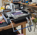
So, I am now the proud owner of a Desktop SMT pick-and-place machine. And although it has its quirks, it's a good machine in general. My only complaint would be the quality of its nozzles, but I'd rather leave those details out of this discussion.

1714753642533.png

What's proving to be a real challenge, though, is learning to use its controller software. The machine uses the Open PNP software, which is of the open source type and is available for download at github. The machine is basically a vanilla-type of XYZ (and C) linear motion CNC gantry with the very valuable added functionality of computer vision that enhances its precision.

The general way in which it basically works is as follows.
  • A database of parts and their individual geometry must be generated
  • A list of feeders must also be generated
  • The machine then consults the user's parts list and their specific placement and orientation
  • It then picks each part from its corresponding feeder using a vacuum nozzle, transports it to a camera, which then takes a picture of the part and calculates its geometry.
  • It then compensates for misalignment and rotation and places the part on its corresponding coordinates on the PCB.

My question here has to do with fiducials. Fiducials are visual references used to accurately define and compensate the coordinates of the job currently being processed. Most commercial PCBs have several fiducials on them for production purposes. And of most fiducials have a basic 1mm diameter circular geometry.

But sometimes a PCB can be so crowded with parts that it's very hard, if not impossible, to place a fiducial in it. In fact, a minimum of two fiducials is required to define a board's coordinate system. So the alternative is to use a part's footprint pads on the PCB as fiducials. And THAT is what I'm having trouble with. I've been struggling quite a bit trying to set this up but I haven't gotten far.

Is anyone here familiar with Open PNP and has faced the same problem?
 

Jerry-Hat-Trick

Joined Aug 31, 2022
596
I'm not familar with Open PNP but I'm trying to picture in my mind a PCB with surface mount components that is so busy there is no room for a few 1mm diameter circles! No room under ICs before they are mounted? If it's multiples of the same circuit on a single PCB which are broken out then have sacrificial strips with fiducials. Or mount the PCB tightly in a frame jig which has fiducials on it? Probably no help, but I'm interested to see what others suggest...
 

Thread Starter

cmartinez

Joined Jan 17, 2007
8,304
I'm not familar with Open PNP but I'm trying to picture in my mind a PCB with surface mount components that is so busy there is no room for a few 1mm diameter circles! No room under ICs before they are mounted? If it's multiples of the same circuit on a single PCB which are broken out then have sacrificial strips with fiducials. Or mount the PCB tightly in a frame jig which has fiducials on it? Probably no help, but I'm interested to see what others suggest...
One of the problems is that the 1mm circles have a 3mm diameter courtyard that must not be invaded by other footprints in order for the machine to easily identify its location.

And on the other hand, the boards have already been manufactured without round fiducials (that will be corrected in the next lot) so I have to figure out a way to use the component's footprints as fiducials. I have been making some progress, but I'm still a long way off from making things work.
 

Thread Starter

cmartinez

Joined Jan 17, 2007
8,304
Apparently, the answer lies in the "pipeline" of the "Fiducial Vision Settings" corresponding to the footprint in particular. From what I'm understanding, the pipeline is the series of steps taken for image processing to arrive at a final interpretation of its geometry and alignment.

But the number of possible steps is quite high and complicated...
 

Thread Starter

cmartinez

Joined Jan 17, 2007
8,304
There you go. I finally got somewhere.

I stopped trying to use a component footprint as a fiducial, and then tested if I could use a through-hole pad instead. What I did, is I copied all the settings specific to the 1mm diameter fiducial, and then created a new part with them. Afterwards, I simply changed the fiducial's diameter to that of the outside of the through-hole pad.

I was afraid that it wouldn't work because of the black gap in the hole. But to my surprise, it worked on the first try! ... one thing though, is that the pad to be used as a fiducial must not be close to another of similar size, because the machine will get confused and start searching around until it reports an error.

Gotta get back to the workshop. Thanks for your interest on this thread. I'll keep documenting my progress here, see if that helps others with similar needs.
 

Thread Starter

cmartinez

Joined Jan 17, 2007
8,304
I ordered 50 PCB's from PCBWay, and they sent me 5 panels of 2x5 boards, which include 4 fiduciaries that should be easy to use in my PNP machine.

When I asked them the exact distribution of the boards and fiduciaries, they handed me a bunch of "production files". None of which are in a format that I can recognize. I simply don't know how to open them so I can view their contents.

Anyone here familiar with that sort of file format?
 

Thread Starter

cmartinez

Joined Jan 17, 2007
8,304
Well, this machine is proving to be definitely not easy to use ... it's very quirky and the software has many many dark spots in its "user manual". I have finally tuned it well enough for it to more or less work reliably. But just as I was going to get serious about producing a couple of hundred PCBs, the vacuum pump overheated and its diaphragm assembly melted on me ... It's not an expensive part to replace, but waiting the two days or so for the spare to arrive is quite frustrating.

One thing I'd like to see, is documentation explaining (with examples included) what each of the vision "pipeline" commands does and their corresponding parameters. But I've looked everywhere and (other than a very few videos in YouTube) haven't found anything useful so far.

Here's the list of all available CV commands:


ActuatorWrite
Add
AffineUnwarp
AffineWarp
BlurGaussian
BlurMedian
ClosestModel
ComposeResult
ConvertColor
ConvertModelToKeyPoints
ConvertModelToPoints
CreateFootprintTemplateImage
CreateModelTemplateImage
CreateShapeTemplateImage
DetectCirclesHough
DetectCircular Symmetry
DetectEdgesCanny
DetectEdgesLaplacian
DetectEdgesRobertsCross
DetectFixedCirclesHough
DetectLinesHough
DetectRectangleHough
DetectRectlinearSymmetry
DilateModel
DrawCircles
DrawContours
DrawEllipses
DrawImageCenter
DrawKeyPoints
DrawRotatedRects
DrawTemplateMatches
FilterContours
FilterRects
FindContours
FitEllipseContours
GrabCut
HistogramEqualize
HistogramEqualize Adaptive
ImageCapture
ImageRead
ImageRecall
ImageWrite
ImageWriteDebug
MaskCircle
MaskHsv
MaskModel
MaskPolygon
MaskRectangle
MatchPartsTemplate
MatchPartTemplate
MatchTemplate
MinAreaRect
MinAreaRectContours
MinEnclosingCircle
Normalize
OrientRotatedRects
ParameterBool
ParameterNumeric
ReadModelProperty ReadPartTemplateImage
Rotate
ScriptRun
SelectSingleRect
SetColor
SimpleBlobDetector
SimpleOcr
SizeCheck
Threshold
ThresholdAdaptive
WritePartTemplateImage​
 
Top