 Facebook
 Google
 GitHub
 Linkedin
Warning! Warning! Will Robinson! SPQR is a neophyte!! 
I present this camera slider project for comments (took me about a year, but I've learned a ton!).
And I thank those of you who helped me with my previous questions on the forum!
Hardware
1" Aluminum square tube - local metal supplier
"T"s and elbows - Lowes
Tripods - Amazon
Screws, bolts, nuts - Lowes, Fastenal
Acrylic - Lowes
1/2" Aluminum angle - Lowes
Ball bearings, 1/2" rod, rod stands, linear bearings - www.VXB.com
Nylon standoffs and screws - www.non-ferrousfastener.com
Camera holder - Amazon
Antivibration material - Sorbothane - www.amazon.com
Pulleys, belt - www.polytechdesign.com


Electronics
Arduino Uno - Sparkfun
Arduino Protoshield - Adafruit
Stepper motor - Vexta PK266-02A - www.interinar.com
Interinar Stepper Controller - BSD-02LH - www.interinar.com
Connectors, headers - Sparkfun, All Electronics, Adafruit
Wire - All Electronics, Jameco, Sparkfun
Power Supply - FS-15024 - Interinar
Absolute Binary Rotary Encoder - Parallax
Micro switches - Adafruit
7809 (9V regulator), 74HC14 (Schmitt trigger), 10K resistor NET, 10μF 16V tantalum capacitors - Jameco
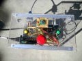
Pictures of the box are attached.
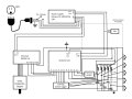
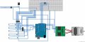
The schematics are attached (One with Fritzing, another with PowerPoint, and a third with PowerPoint of the hardward debouncing only).
Code
-------------------------------------------
Lessons Learned / Comments
1. Build the hardware first. Before the use of a belt and pulleys, I used an Acme threaded rod. It sounded like a brass band. NOISY!
2. The belt and pullies were much better, but because of the long pieces of aluminum, they tended to resonate, so I "padded" the motor with Sorbothane - fantastic material!
3. The final "quieting" step was changing the stepping. Though 1/8th step on a stepper gives more torque, it also makes a lot of noise - stick with full step if you can.
4. Use as many connectors as you can (I need to learn more about connectors). In future, I'll even be adding a connector very close to the stepper to allow quick changeouts.
5. The initial version had all the non-Arduino electronics on a perfboard. It was UGLY. So I learned to use a protoboard whenever possible with Arduino projects.
6. After "finishing" my early version, I noted that the it used to go back and forth for no reason. I turned on the serial port in Arduino as a debugger, and programmed some observation bits, finding random "1"'s popping up when there should have been only "0"s. I thought about software debouncing. Then, while googling, I found the phrase "hardware debouncing" and it changed everything! A capacitor, resistor and a Schmitt trigger for every switch made it work right. I'll use hardware debouncing for every switch in future projects.
7. I was going to use a grey code encoder, but the programming looked like a large project, so I found the Parallax Absolute Binary Encoder. It's been taken off the market (not sure why), so I'll work on learning how to program a grey code knob.
8. The little bearings for the pulley on the distal end work very nice.
9. I HATE working with acrylic. The "glue" at Lowes doesn't hold worth beans, so I added those 1/2" aluminum angles throughout for strength. The acrylic I chose is too thin.
10. I used a 7809 regulator, only because I know the 78XX series from many moons ago. I'm sure there is something better now.
11. If I had a TIG welder, I probably would have welded the frame together (I only have a MIG).
12. Had a tough time finding the screws for the micro-switches. If anyone is interested, they are #2 machine screws.
13. For those who have never cut aluminum, thin-walled stuff cuts fine on a carbide wood saw.
14. You can have NO GAP in the two DB-9 connectors, otherwise you will have a bad connection. Initially, I put the acrylic between the two connectors, but it was a disaster. Had to move the internal DB-9 to outside, then it worked fine.
15. The linear bearings occasionally need a bit of WD40.
16. Initially, I planned to use one of those 9V plug connectors for power to the Arduino, then by chance I saw the "Vcc" input terminal on the board, and used it instead.
Link to YouTube video
I have a total of 379 questions for you, but I'll not be a boor, and ask just four:
Questions for the Experts
1 - How do the experts make their "containers" for projects? Is there a place to buy them pre-made?
2 - Is there a treatise I can read on connectors? Which connectors to use, and where?
3 - How do I select the guage of wire for different parts of projects, and when do I use solid vs stranded?
4 - Do you consider the use of "headers" and "pins" part of a final product? Or should everything be soldered to a board?
------------
I await your comments...
I present this camera slider project for comments (took me about a year, but I've learned a ton!).
And I thank those of you who helped me with my previous questions on the forum!
Hardware
1" Aluminum square tube - local metal supplier
"T"s and elbows - Lowes
Tripods - Amazon
Screws, bolts, nuts - Lowes, Fastenal
Acrylic - Lowes
1/2" Aluminum angle - Lowes
Ball bearings, 1/2" rod, rod stands, linear bearings - www.VXB.com
Nylon standoffs and screws - www.non-ferrousfastener.com
Camera holder - Amazon
Antivibration material - Sorbothane - www.amazon.com
Pulleys, belt - www.polytechdesign.com
Electronics
Arduino Uno - Sparkfun
Arduino Protoshield - Adafruit
Stepper motor - Vexta PK266-02A - www.interinar.com
Interinar Stepper Controller - BSD-02LH - www.interinar.com
Connectors, headers - Sparkfun, All Electronics, Adafruit
Wire - All Electronics, Jameco, Sparkfun
Power Supply - FS-15024 - Interinar
Absolute Binary Rotary Encoder - Parallax
Micro switches - Adafruit
7809 (9V regulator), 74HC14 (Schmitt trigger), 10K resistor NET, 10μF 16V tantalum capacitors - Jameco
Pictures of the box are attached.
The schematics are attached (One with Fritzing, another with PowerPoint, and a third with PowerPoint of the hardward debouncing only).
Code
Rich (BB code):
///////////////////////////////////////////////////////////////////
// Camera Slider code
// The Interinar controller should be set at "full step"
// because it makes less noise
////////////////////////////////////////////////////////////////

const int Encoder_PIN_1 = 2;
const int Encoder_PIN_2 = 3;
const int Encoder_PIN_3 = 4;
const int Encoder_PIN_4 = 5;

const int Forward_PIN = 6;
const int Back_PIN = 8;
const int Stop_PIN = 7;
const int Origin_PIN = 10;
const int End_PIN = 9;

const int STEP_PIN = 11;
const int Enable_PIN = 12;
const int DIR_PIN = 13;

int RotationSpeed;
int Stop;
int Forward;
int Back;
int Origin;
int End;

void setup()
{
   pinMode(STEP_PIN, OUTPUT);
   pinMode(Enable_PIN, OUTPUT);
   pinMode(DIR_PIN, OUTPUT);
   pinMode(Encoder_PIN_1, INPUT);
   pinMode(Encoder_PIN_2, INPUT);
   pinMode(Encoder_PIN_3, INPUT);
   pinMode(Encoder_PIN_4, INPUT);
   pinMode(Forward_PIN, INPUT);
   pinMode(Back_PIN, INPUT);
   pinMode(Stop_PIN, INPUT);
   pinMode(Origin_PIN, INPUT);
   pinMode(End_PIN, INPUT);
   digitalWrite(Enable_PIN, HIGH); //When device turned on, stepper is off
   digitalWrite(DIR_PIN, HIGH);
}

void loop()
{
   Stop = digitalRead(Stop_PIN);
   if (Stop == HIGH) {digitalWrite(Enable_PIN, HIGH);}

   Forward = digitalRead(Forward_PIN);
   if (Forward == HIGH) {digitalWrite(Enable_PIN, LOW);
      digitalWrite(DIR_PIN, HIGH);}

   Back = digitalRead(Back_PIN);
   if (Back == HIGH) {digitalWrite(Enable_PIN, LOW);
      digitalWrite(DIR_PIN, LOW);}

   Origin = digitalRead(Origin_PIN);
   if (Origin == HIGH)
      {
          digitalWrite(Enable_PIN, LOW);
          digitalWrite(DIR_PIN, HIGH);
       }

   End = digitalRead(End_PIN);
   if (End == HIGH)
      {
         digitalWrite(Enable_PIN, LOW);
         digitalWrite(DIR_PIN, LOW);
       }

   int Pin1 = digitalRead(Encoder_PIN_1);
   int Pin2 = digitalRead(Encoder_PIN_2);
   int Pin3 = digitalRead(Encoder_PIN_3);
   int Pin4 = digitalRead(Encoder_PIN_4);

   //The following formula was empirically derived
   //If the dial is set to "zero" the lowest speed is 210 (interval between   pulses)
   //If the dial is set to "16" the highest speed is 60
   RotationSpeed = 220 - (10 * (1 + ( (Pin1*8) + (Pin2*4) + (Pin3*2) + Pin4) ) );

   //RotationSpeed = 300; //use this line for testing and comment out the line above

   for (int i=0; i < 100; i++)
      {
         digitalWrite(STEP_PIN, HIGH);
         delayMicroseconds(RotationSpeed);
         digitalWrite(STEP_PIN, LOW);
         delayMicroseconds(RotationSpeed);
       }
}Lessons Learned / Comments
1. Build the hardware first. Before the use of a belt and pulleys, I used an Acme threaded rod. It sounded like a brass band. NOISY!
2. The belt and pullies were much better, but because of the long pieces of aluminum, they tended to resonate, so I "padded" the motor with Sorbothane - fantastic material!
3. The final "quieting" step was changing the stepping. Though 1/8th step on a stepper gives more torque, it also makes a lot of noise - stick with full step if you can.
4. Use as many connectors as you can (I need to learn more about connectors). In future, I'll even be adding a connector very close to the stepper to allow quick changeouts.
5. The initial version had all the non-Arduino electronics on a perfboard. It was UGLY. So I learned to use a protoboard whenever possible with Arduino projects.
6. After "finishing" my early version, I noted that the it used to go back and forth for no reason. I turned on the serial port in Arduino as a debugger, and programmed some observation bits, finding random "1"'s popping up when there should have been only "0"s. I thought about software debouncing. Then, while googling, I found the phrase "hardware debouncing" and it changed everything! A capacitor, resistor and a Schmitt trigger for every switch made it work right. I'll use hardware debouncing for every switch in future projects.
7. I was going to use a grey code encoder, but the programming looked like a large project, so I found the Parallax Absolute Binary Encoder. It's been taken off the market (not sure why), so I'll work on learning how to program a grey code knob.
8. The little bearings for the pulley on the distal end work very nice.
9. I HATE working with acrylic. The "glue" at Lowes doesn't hold worth beans, so I added those 1/2" aluminum angles throughout for strength. The acrylic I chose is too thin.
10. I used a 7809 regulator, only because I know the 78XX series from many moons ago. I'm sure there is something better now.
11. If I had a TIG welder, I probably would have welded the frame together (I only have a MIG).
12. Had a tough time finding the screws for the micro-switches. If anyone is interested, they are #2 machine screws.
13. For those who have never cut aluminum, thin-walled stuff cuts fine on a carbide wood saw.
14. You can have NO GAP in the two DB-9 connectors, otherwise you will have a bad connection. Initially, I put the acrylic between the two connectors, but it was a disaster. Had to move the internal DB-9 to outside, then it worked fine.
15. The linear bearings occasionally need a bit of WD40.
16. Initially, I planned to use one of those 9V plug connectors for power to the Arduino, then by chance I saw the "Vcc" input terminal on the board, and used it instead.
Link to YouTube video
I have a total of 379 questions for you, but I'll not be a boor, and ask just four:
Questions for the Experts
1 - How do the experts make their "containers" for projects? Is there a place to buy them pre-made?
2 - Is there a treatise I can read on connectors? Which connectors to use, and where?
3 - How do I select the guage of wire for different parts of projects, and when do I use solid vs stranded?
4 - Do you consider the use of "headers" and "pins" part of a final product? Or should everything be soldered to a board?
------------
I await your comments...
Attachments
-
 70.9 KB Views: 336
 -
 305.6 KB Views: 284
 -
 25.3 KB Views: 212
 -
 59.8 KB Views: 276
 -
 56 KB Views: 249
Last edited:


