9th order low pass butterworth filter

Thread Starter

ajaysathya2604

Joined May 29, 2018
9
Hello,

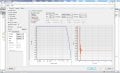
I am designing a 9th order low pass butterworth filter. I have created the design at the moment. I would like to Know if an addition of a 5th and 4th order IC low pass filter would create a 9th order filter or should it be 2+2+2+2+1 like the usual way. I would like to use ICs available in the market to make this filter.
 

Attachments

crutschow

Joined Mar 14, 2008
34,284
Know if an addition of a 5th and 4th order IC low pass filter would create a 9th order filter or should it be 2+2+2+2+1 like the usual way.
Combining two or more Butterworth filters does not give you a Butterworth filter.
All the filters in the chain have to be configured to give the proper Butterworth response at the output.

You could likely use one of these.
 

OBW0549

Joined Mar 2, 2015
3,566
Yes, I understand that. Im looking forward to make the design as compact as possible.
Keep in mind that while synthesis of a 9th-order filter, such as what you show in the diagram attached to your post, is rather easy (given appropriate filter design software), actual implementation of the design will be extremely difficult if not outright impossible due to the requirement for either extremely tight-tolerance components (which are expensive) or a lot of labor-intensive trimming to get the desired response. Or both.
 

danadak

Joined Mar 10, 2018
4,057
For sure the solution I posted earlier is only good to < 100Khz. Ignore
that post. The DSP solution for a Mhz type of filter would be the advanced
TI DSP parts, or Analog Devices or FPGA solutions.

Regards, Dana.
 

Thread Starter

ajaysathya2604

Joined May 29, 2018
9
So, from the comments I understand that my simulated filter design is really hard to implement and receive results similar to that of the simulations. Would it be a optimal to add a passive filter as mentioned above? If yes, what would be the setbacks?
 

DECELL

Joined Apr 23, 2018
96
The active filter need some very fast opamps and close attention to layout an it is unlikely to perform well on a breadboard. Stray capacitance and inductance will make your life hell!
If you go with the passive you can easily set the input and output impedance to suit your application.
You may want to relax on pass band ripple to keep it simple.
Sticking to preferred component values gives you a good enough result most of the time. eg:
upload_2018-5-30_15-20-11.png
 

danadak

Joined Mar 10, 2018
4,057
Pros and cons active vs passive filter design -

1) - No Ls required (generally), active.
2) - Generally smaller design volume wise, lower weight, mass, active.
3) - Lower Noise (you have to do the analysis, this result is not chiseled in stone), passive.
4) - Less components (generally), passive.
5) - No external power needed, passive, although you may need an amp to compensate for losses.
6) - No nonlinearities,. passive, but microphonics in magnetics can present as noise, non linearity.
7) - Higher and lower temp operation, passive.

I am sure there are more.

Regards, Dana.
 
Last edited:
Top