8x8 power port array (mosfet controlled)

Thread Starter

Kelly Sumrall

Joined Jun 13, 2015
8
Hello,

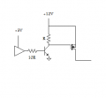
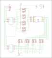
I'm building a micro controller controlled power module that will operate 64 individual power ports. This is to be used as a firework ignition sequencer. Each power port will ignite an electronic match, one at a time. There will not be more than one port on at a time. The power matrix is to be powered by its own battery supply and controlled through data lines by the micro controller. I've just started learning about mosfets and they seem to fit the bill. The provided schematic shows what I think to be a good start using 595 shift registers, p-channel and n-channel mosfets to control the current flow in the array. The problem is...I can't get it to work on my test array breadboard project. I'm missing something, maybe a lot. Can someone review the schematic and let me know if the principle is sound.

Thank you
 

Attachments

AnalogKid

Joined Aug 1, 2013
10,987
The outputs of the 595's can not go above 6 V, but the P-channed FETs have sources tied to +12 V. With Vgs=-7, all 8 P-channels probably are on at the same time. One solution for this is 8 NPN transistors as open collector drivers/level translators between the upper 595 and the Pch's, with 8 base resistors and 8 pullup resistors from the gates to +12V. There are quad NPN transistor arrays, and octal NPN transistor arrays with base resistors integrated into one package (ULN2803). In this application the NPN is an inverter, so you will need to shift in an inverted word for upper register.

What is the current you are controlling? If it is below 0.5 A, you can replace the four, dual N-channel MOSFETs with a 2803.

ak
 
Last edited:

Thread Starter

Kelly Sumrall

Joined Jun 13, 2015
8
After reviewing my attachment at work and based on #12s comments, I'm attaching the datasheets for the two mosfets and what I hope to be a better rendition of the schematic.

AnalogKid, as for the current, I think it will be at least an amp based on previous experiments. I've tried to measure the resistance of a couple of emathes and it is about 10 ohms. I think that rules out the ULN2803 which, based on the datasheet, has a max current of 500mA. I'm still trying to grasp the ideas of your suggestion with the NPN transistor and how the Vgs = -7. I'm going to do some more research on working with p-channel mosfets and get back.
 

Attachments

#12

Joined Nov 30, 2010
18,224
I believe this is what AnalogKid said.
Is this enough to start you or do you need me to explain parts of it?

Edit: Oops. That 10R should be more like 4R
 

Attachments

Last edited:

Thread Starter

Kelly Sumrall

Joined Jun 13, 2015
8

AnalogKid

Joined Aug 1, 2013
10,987
You've got the idea. For bipolar drivers you can use just about anything, 2N4401, 2N3904, 2N2222, etc., singly or in quad arrays. Or you can use a small MOSFET like 2N7000 or 7002, and eliminate the base resistor.

ak
 

Thread Starter

Kelly Sumrall

Joined Jun 13, 2015
8
I thought I'd try something when I got home. I bypassed the NPN transistor that controlled the gate of the PMOS (is there a proper name for that type of device function ie shunt?) and altered the software to output a 0 on the 595 shift register for the PMOS pins. This basically removes a transistor and a resistor for each PMOS, and it works! The low value on the 595 seems to bring the PMOS gate to ground and turns on the chip.
Are there any disadvantages to this circuit design other than the software needing to invert the bits for the PMOS chips?
 

Attachments

#12

Joined Nov 30, 2010
18,224
According to my education, that is not happening because you can't put 12 volts on the output pin of a chip that is operating from a 5 volt supply. There is an output HiZ state cause by "output enable (Hi)", but that seems to apply to all outputs when you command: Hi, therefore, none of the outputs can change state.

Problem: I am an analog person. If the datasheet showed me how the outputs are built, I would know for sure. All I have to go on is what I've learned by accident, but...read my signature...

Edit: After a bit of Googling, I still can't see how that can possibly work.
Anybody else know the answer???
 
Last edited:

AnalogKid

Joined Aug 1, 2013
10,987
Are there any disadvantages to this circuit design other than the software needing to invert the bits for the PMOS chips?
Yes. As mentioned in post #3, those 10K resistors are putting 12 V on the 595 output pins whenever they are in the high state or when the 595 outputs are tristated. The 10K resistance limits the available current, but this still is a bad design that will not have long-term reliability.

Look at it this way - it makes the programming easier. With driver transistors between the upper 595 and the upper power MOSFETs, a logic 1 turns on a row. This is the same logic polarity as the column data in the lower 595.

ak
 

Thread Starter

Kelly Sumrall

Joined Jun 13, 2015
8
After making some progress with this project, I'm back for more advise. I have put together a schematic of the main circuit that will be controlled by the microprocessor. Can someone review the schematic and let me know if it is sound in principal. I know there is work to be done to make the schematic more professional and I'd like any feedback in that area as well. I'd like to add this to the finished projects section one of these days. Since this if for a firework display and I'm not going to make it for this 4th of July, I'm shooting for New Years. If anybody is interested, I've provided a zip of the evolving KiCad project files. Please feel free to review them as well and offer any advice or critisism. I'm a noob at all this and can use the help and guidance.

Kell
 

Attachments

Top