7805 appears to not be working - any ideas?

Thread Starter

PotatoClock

Joined Apr 29, 2017
5
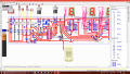
This is a long shot but I wanted to try anyway. Over the past year I've been working on my A2 coursework. For part of it I had to design a circuit using Circuit Wizard 2.0. Designed it, went through everything, made the PCB, soldered everything in and ironed out the mistakes I made when I was doing that. Here's the hard part - For some reason the 0V rail is receiving around 7-8V. I can't find why this is happening, there is no connection to the positive, and I've checked for a stray wire or loose connection. I'm out of ideas on what it could be and so is my teacher. Also, in my class of 9, only one other person has their circuit working, all of the others have a myriad of faults for no apparent reason. Could it be that my school uses cheap components or have i made a mistake in designing my circuit? I replaced the original 7805 with another but same problem.

In the post which led me to this website (link: https://forum.allaboutcircuits.com/threads/lm317-vs-7803.37268/ ) I saw that the capacitors needed were 0.33uF and 0.10uF. I was told to use 0.10uF capacitors for both, so could this be the problem? Any help at all would be hugely appreciated, thanks.
 

dl324

Joined Mar 30, 2015
16,943
Welcome to AAC!

Post a schematic of your circuit with relevant voltages marked.

Your post would be easier to read if you used paragraphs...
 

Thread Starter

PotatoClock

Joined Apr 29, 2017
5
Welcome to AAC!

Post a schematic of your circuit with relevant voltages marked.

Your post would be easier to read if you used paragraphs...
Yea sorry about that, doing this all in a bit of a panic

Here's a screenshot of the PCB on circuit wizard. Sorry it's a bit blurry, best I can do. I'd upload the file but I can't when I try to. The circuit uses 9V battery and it all turns on in real life, it's connected to seven segment displays and they work, but the problem is that because of the positive negative rail, the PIC won't work, though strangely the 4026b's do
upload_2017-4-29_19-51-39.png
 

Attachments

Ford Prefect

Joined Jun 14, 2010
245
I am interested with this. But the screenshot is not showing the full circuit. Did you design and build this on the PCB sheet of Circuit Wizard or did you design the circuit on the Circuit Design sheet and use the application to convert to a PCB?
I think the answer is the former not the latter. But if you do have a schematic it will be easier to work out where the problem is. Can you post a schematic diagram?
 

Thread Starter

PotatoClock

Joined Apr 29, 2017
5
I am interested with this. But the screenshot is not showing the full circuit. Did you design and build this on the PCB sheet of Circuit Wizard or did you design the circuit on the Circuit Design sheet and use the application to convert to a PCB?
I think the answer is the former not the latter. But if you do have a schematic it will be easier to work out where the problem is. Can you post a schematic diagram?

I designed a circuit schematic but had to manually design the PCB.
upload_2017-4-29_20-16-18.png

upload_2017-4-29_20-16-35.png
upload_2017-4-29_20-17-0.png
 

Attachments

Thread Starter

PotatoClock

Joined Apr 29, 2017
5
The circuit diagram you attached to post #10 does not match the PCB layout.
I know, part of having to make the PCB manually (not my choice) was that things that worked with the circuit design wouldn't work with the PCB design, because I needed to keep the number of flying wires down
 

dl324

Joined Mar 30, 2015
16,943
Here's a screenshot of the PCB on circuit wizard. Sorry it's a bit blurry, best I can do. I'd upload the file but I can't when I try to.
Post a schematic that includes the voltage regulator and the voltages you're measuring.

If you can't post a file, cut and paste the information.
 

Ford Prefect

Joined Jun 14, 2010
245
Post a schematic that includes the voltage regulator and the voltages you're measuring.

If you can't post a file, cut and paste the information.
Agreed.
At first sight I doubt if it has anything to do with the 7805 but certainly D9 is the wrong way round. I am suspecting that when you built this, a component or a wire connection is incorrect.
 

Alec_t

Joined Sep 17, 2013
14,335
IC1 (whatever it is?) seems to have some floating data inputs (D0, D1), and Q2 (an output?) is shorted to the +ve rail by the switch SW3.
 
Top