 Facebook
 Google
 GitHub
 Linkedin
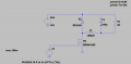
I want to design a buck converter for E-bike with 75V input and 12V,20A(240W ideal case) output to drive the other components of E-bike using n-mosfet as a low side, i also want to use a feedback using a microcontroller to adjust the output voltage to 12V when the load vary?
Attachments
-
 16.4 KB Views: 7


