74AHCT vs 74LVC SOLVED!

Thread Starter

schmitt trigger

Joined Jul 12, 2010
2,085
I've posted over 1200 messages in this forum alone, and I believe this is my first time asking a question.

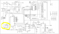
I designed and built a multi-frequency reference derived from a 10 Mhz OXCO which optionally can use an external 10 Mhz reference signal.
  1. The circuit has worked flawlessly for 5+ years. Schematic attached. This IS NOT the issue.
  2. I always purchase legit components from Digikey or Mouser. No Ebay or Amazon wannabes.
  3. The board is fed from a well regulated +5V, and every single device has its own ceramic decoupling located no more than 0.1" away.
  4. The board is a 4 layer board with a dedicated power and ground plane.
  5. The output is driven via a tri-state buffer, 74AHCT1G125. Which only delivers +/-8 mA. Yellow highlight in the schematic.
  6. I required a larger drive, and decided to replace it with a 74LVC1G125, which can provide +/-24 mA.
  7. For your convenience I include the datasheets for both. I read them, and the only significant differences I can tell are the Vih, Vil, Voh and Vol levels.
 

Attachments

Last edited:

Thread Starter

schmitt trigger

Joined Jul 12, 2010
2,085
So what my problem then? When replacing the 74AHCT with the 74LVC device, after a few seconds of operation, unloaded, the input becomes low impedance and the signal vanishes.
Mind you, after soldering the device and before applying power I had checked the solder joints with a stereo microscope and also checked continuity.
I thought that perhaps I had damaged the 74LVC device, so I removed it and installed a brand new one. Same result.
Then I re-installed the original 74AHCT, and again it is working fine!

I know that there is something that I must have overlooked, but cannot figure what. From the datasheets, the devices should be compatible.
 

Thread Starter

schmitt trigger

Joined Jul 12, 2010
2,085
Are there bypass and filter capacitors close to the buffer chip?
Yes, I mentioned it on one of the bullet points.

The weird thing is that this circuit has worked for over 6 years. Replacing the very last device in the signal chain from an ACHT to a LVC technology causes the device itself to fail, yet replacing it back to the original ACHT the circuit becomes functional again….nothing else has broken.

Weirdest still is that the failure takes about 10 seconds to manifest itself.
To Crut’s question, yes, the logic levels are less than 100 mV from the respective rails… well within LVC specs. As a fact, that was the very first thing I checked as the only significant datasheet difference are the Voh and Vol values.
 

nsaspook

Joined Aug 27, 2009
16,321
Yes, I mentioned it on one of the bullet points.

The weird thing is that this circuit has worked for over 6 years. Replacing the very last device in the signal chain from an ACHT to a LVC technology causes the device itself to fail, yet replacing it back to the original ACHT the circuit becomes functional again….nothing else has broken.

Weirdest still is that the failure takes about 10 seconds to manifest itself.
To Crut’s question, yes, the logic levels are less than 100 mV from the respective rails… well within LVC specs. As a fact, that was the very first thing I checked as the only significant datasheet difference are the Voh and Vol values.
Yes, you did...
It doesn't see obvious. I've seen weird system errors when device ground connections were high resistance or open. Leakage currents keep lower power devices functioning for X configuration but changes that need more current cause lockups and device malfunctions as current/power flows reverse thru input pins and such.
 

sparky 1

Joined Nov 3, 2018
1,218
Possibly the picaxe-20X2 defaults to the low level 4X the external clock designed for the low level HCT touch level.
when replaced with the 74LVC125 the much higher level might be changing the programmed default to something
it cannot recognize, could be outside the window that the pause statements can use to calibrate.
Using a function generator and attenuation try to mimick the 74AHCT125 output try verify what the problem is
and find a way around preset 8MHz internal clock defaulting to 32MHz I think uses PLL
 

Thread Starter

schmitt trigger

Joined Jul 12, 2010
2,085
Thanks everyone. I DO INTEND to understand the root cause and I will definitely share whatever I find with this group.

I don’t want to desolder and resolder ICs from the board anymore, have already done it several times and I risk damaging it. And as I mentioned previously, the circuit is now working perfectly as it ever was with the 74AHCT.

What I plan to do is to design and order small test boards from JLCPCB, then order a bunch of 74xxx125 devices from both the AHCT and LVC variants, as they are only $0.11 each, and then torture the hell out of them.
 

nsaspook

Joined Aug 27, 2009
16,321
Thanks everyone. I DO INTEND to understand the root cause and I will definitely share whatever I find with this group.

I don’t want to desolder and resolder ICs from the board anymore, have already done it several times and I risk damaging it. And as I mentioned previously, the circuit is now working perfectly as it ever was with the 74AHCT.

What I plan to do is to design and order small test boards from JLCPCB, then order a bunch of 74xxx125 devices from both the AHCT and LVC variants, as they are only $0.11 each, and then torture the hell out of them.
OK, usually when I see something weird like this I try to make a simple test board like you said to recreate the failure. Good luck and good hunting.
 

Thread Starter

schmitt trigger

Joined Jul 12, 2010
2,085
SOLVED! A perfect example of serendipity.

I was reading the article linked at the bottom, basically how an emitter follower can oscillate at the VHF range. The takeaway from this article was that digital scopes are not the best tools to view spurious high frequency oscillations, more so if the waveform it is triggered to is of low frequency. The best tool, unless one has an ultra- fancy DSO, is an analog scope.
Thus I brought out my trusty Tek 2211.
And now I could clearly see it. With the 74LVC device, there is a wild oscillation, not present with the 74AHCT variant. That caused its demise.
I had to eat some humble pie: while I had been confident that my board layout was 1000% perfect, it turns out that for the LVC device it wasn’t good enough.
That reminds me of the three most important considerations for a high speed board design: layout, layout, layout. I will have to redesign the board if I ever want to switch to the LVC device.
And the most important takeaway is that analog instruments still have a place in my workbench.

https://entertaininghacks.wordpress...ier-solderless-breadboards-and-oscilloscopes/
 

nsaspook

Joined Aug 27, 2009
16,321
SOLVED! A perfect example of serendipity.

I was reading the article linked at the bottom, basically how an emitter follower can oscillate at the VHF range. The takeaway from this article was that digital scopes are not the best tools to view spurious high frequency oscillations, more so if the waveform it is triggered to is of low frequency. The best tool, unless one has an ultra- fancy DSO, is an analog scope.
Thus I brought out my trusty Tek 2211.
And now I could clearly see it. With the 74LVC device, there is a wild oscillation, not present with the 74AHCT variant. That caused its demise.
I had to eat some humble pie: while I had been confident that my board layout was 1000% perfect, it turns out that for the LVC device it wasn’t good enough.
That reminds me of the three most important considerations for a high speed board design: layout, layout, layout. I will have to redesign the board if I ever want to switch to the LVC device.
And the most important takeaway is that analog instruments still have a place in my workbench.

https://entertaininghacks.wordpress...ier-solderless-breadboards-and-oscilloscopes/
That's why I keep my trusty TEK. I trust it to see the universe, unaltered.
1736364808804.png

The quality/type of the bypass/decoupling capacitors is important in designs with wide bandwidth devices. The self-resonant frequency of a typical 0.1uf SMD unit might be the low-VHF range so I've often added a 1000pf 0603 bypass on top of a 805 on critical bypass circuits later if I see possible signal issues.
1736366576180.png
 

Thread Starter

schmitt trigger

Joined Jul 12, 2010
2,085
That is an excellent suggestion!

An anecdote; back in the early 1990s I worked for a company manufacturing analog video processing. NTSC and PAL.

We had some Tek scopes with advanced triggering capabilities, where one could dial in the exact raster line to be viewed, but because the extremely low 1/525 duty cycle, the display would be very dim. The engineers would thus prefer digital scopes with identical triggering capabilities but with nice, bright displays.

One day we received a bunch of brand new malfunctioning units. Normal video would be just fine, however with SMPTE color bars the sync would go haywire. Hours and hours troubleshooting and no anomalies would be seen. That is until someone brought out the analog scope.
It turns out that on the green to magenta transition, which has 180 degree phase shift, our circuit was creating a spurious pulse that would drop to the blacker than black level, that is, sync pulse territory.
The green to magenta transition was always very tough for color TVs, on most of them there would be a dark vertical line caused by the luminance overshoot. As long as it didn’t get below 0 IRE, it was of no concern IMG_0525.jpeg
 
Top