Facebook
 Google
 GitHub
 Linkedin
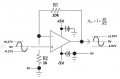
Yo guys i have a 741 ic issue.
R2 (at the bottom)= 10kohm
R1 = 1kohm
Differential V - / v+ = 8v
With respect to the gain formula the gain result should be 11.
On the Imput side i have 100mV so on the output i should normally get 1,1V. And im getting 0 instead so what the heck is that.
I changed the ic 3 times. So its not the ic. What am i doing wrong ?
Attachments
-
 4 MB Views: 27