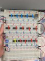
My question is how would I connect D0 and D1 on the first AND gate with D2 and D3 on the second AND gate. ( further questions would be ask)
Blue mark = 74LS32
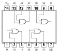
Red mark = 74LS08
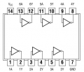
Yellow mark = 74LS04
Blue mark = 74LS32
Red mark = 74LS08
Yellow mark = 74LS04
Attachments
-
 297.4 KB Views: 38
 -
 138.2 KB Views: 33
 -
 156.5 KB Views: 30