5v to 24 v switch using transistor

Thread Starter

Jpnagaraj

Joined Mar 8, 2020
25
For a load current of 500mA the datasheet of the MJ2955 shows a base current of 50mA. Any little NPN transistor (BC547, 2N3904, 2N2222, etc) can have a collector current of 50mA when its base current is 5mA.

The base voltage of the little transistor is 0.7V when it is turned on, so if the input from the microcontroller is 5V (it might be 4V when loaded with 5mA) then the base resistor is (5V - 0.7V)/5mA= 860, use 820 ohms.
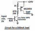
Thankyou i dont have a clear idea of the resistor to be changed can u give me a circuit diagram for high side switching using transistor kindly help me out
 

Thread Starter

Jpnagaraj

Joined Mar 8, 2020
25
Here is the circuit:
Thankyou i tried the circuit which u gave but when i gave 5 v input the output is 4 millivolt jumping till 16 millivolt when i give 0v also i got the same output. i also change the bc547 and mj2955 i could not derive the output and the voltage at the base of bc547 is 750millivolt, and the voltage at the base of mj2955 is 8v.
 

Audioguru again

Joined Oct 21, 2019
6,705
If the supply is +24V and the base of the MJ2955 is +8V then the base-emitter of the MJ2955 has 16V and is destroyed. Since the collector of the MJ2955 is always near 0V then it never turns on.

The datasheet of the MJ2955 shows a maximum base-emitter voltage of 1.5V when its collector current is 4A and its base current is 400mA but your currents are much less. The typical Vbe at your collector current of 500mA is shown as 0.75V. Then the base voltage of the turned-on MJ2955 will be 24V -0.75V= 23.25V. When the MJ2955 turns off then its base voltage will be +24V.

What resistance is your load? It should be 24V/500mA= 48 ohms at more than 12W.
 

KeithWalker

Joined Jul 10, 2017
3,097
I just ordered an old 1965 book on semiconductors and their circuits. I hope it's a really good book, they sure where able do make great analog stuff in the 1960's, true pieces of work and art. So I hope the book is in a form I'll like and is good.
A 1965 book on transistors will probably only discuss the workings of germanium transistors. Silicon transistors were not very available to the hobbyist until the late 60s.
Keith
 

Thread Starter

Jpnagaraj

Joined Mar 8, 2020
25
If the supply is +24V and the base of the MJ2955 is +8V then the base-emitter of the MJ2955 has 16V and is destroyed. Since the collector of the MJ2955 is always near 0V then it never turns on.

The datasheet of the MJ2955 shows a maximum base-emitter voltage of 1.5V when its collector current is 4A and its base current is 400mA but your currents are much less. The typical Vbe at your collector current of 500mA is shown as 0.75V. Then the base voltage of the turned-on MJ2955 will be 24V -0.75V= 23.25V. When the MJ2955 turns off then its base voltage will be +24V.

What resistance is your load? It should be 24V/500mA= 48 ohms at more than 12W.
What you said was absolutely correct this is what happening in my circuit the load i will connect is a relay of 24v and it is a basic relay or the 24v will be given to plc as input when i give 5 v from my controller the output must be 24v and this 24v must be capable of driving a relay or it will be just a input to plc and when given 0v it must be 0v . Should i change the mj2955 or go with any other ic can you suggest me.
 

DarthVolta

Joined Jan 27, 2015
521
The beta (current gain) is used when a transistor is an amplifier with plenty of Vce (4V here) not when it is used as a saturated switch. As a saturated switch almost every datasheet says the base current should be 1/10th the collector current.
Yeah I know the basic sat. model, but I not used to power transistor, which reminds me , need to buy some real 3055/PNP because mine are the junk ebay clones

OP wqhere did u get your's btw ? My cheap ones are underrated, (I fired 2-3)
 

MaxHeadRoom

Joined Jul 18, 2013
28,698
in my circuit the load i will connect is a relay of 24v and it is a basic relay or the 24v will be given to plc as input when i give 5 v from my controller the output must be 24v and this 24v must be capable of driving a relay or it will be just a input to plc and any other ic can you suggest me.
Just curious why you would not considering a logic gate level Mosfet, per post #2 & #7 if needing an alternative option?
Max
 

ebeowulf17

Joined Aug 12, 2014
3,307
Thankyou i tried the circuit which u gave but when i gave 5 v input the output is 4 millivolt jumping till 16 millivolt when i give 0v also i got the same output. i also change the bc547 and mj2955 i could not derive the output and the voltage at the base of bc547 is 750millivolt, and the voltage at the base of mj2955 is 8v.
You must've had a wiring error, or perhaps a component that was already damaged or defective. @Audioguru again 's circuit looks right to me, and his descriptions are spot-on. If you got the outputs and base voltage measurements you described, something has gone wrong.

I'd suggest you very carefully re-check all of your working and make sure it's correct. Once you're sure your working matches the schematic, replace the damaged transistor(s?) and retest.
 

ebeowulf17

Joined Aug 12, 2014
3,307
Just curious why you would not considering a logic gate level Mosfet, per post #2 & #7 if needing an alternative option?
Max
I agree this is a good spot for a MOSFET or two, although I'm not sure about logic level. Using a MOSFET for the output stage eliminates the high base current requirements in the circuit above, meaning you no longer need a big 2W resistor!

The thread starter has already said high side switching, which means a P MOSFET, but you can't control that directly with the microcontroller.
So, you'll need either an NPN BJT or a logic level N MOSFET between the micro and the P MOSFET. In that case, the P MOSFET doesn't need to be logic level, since it will have roughly 24V available for gate voltage, and most logic level devices I've seen don't like exceeding 20Vgs. So it seems like the gate drive requirements actually get more complicated if you go logic level on the output than if you don't.

Or am I missing something here? If either of you can post a circuit switching high side with a single MOSFET, I'd love to know how. Alternately, if using multiple transistors, I'd like to know what advantage, if any, there is to using logic level gate on the P channel device.
 

Audioguru again

Joined Oct 21, 2019
6,705
Why does your 24V relay coil need 500mA? Then it gets very hot with 12W (!). When I used 24V relay coils they used only 35mA.
Since your load is an inductor then it needs a reversed diode parallel with it to clamp the very high voltage it produces when it is switched off.
 

Thread Starter

Jpnagaraj

Joined Mar 8, 2020
25
Why does your 24V relay coil need 500mA? Then it gets very hot with 12W (!). When I used 24V relay coils they used only 35mA.
Since your load is an inductor then it needs a reversed diode parallel with it to clamp the very high voltage it produces when it is switched off.

Sorry for the delay due to covid-19 issues it took time for me to get new components and test it now i got the component the circuit which u gave was working fine and thankyou for the effort u have put now its working fine the issue was with the component and the supply which i used was not a good one so i changed everything and now i got it working fine
 
Top