Facebook
 Google
 GitHub
 Linkedin
Hello folks,
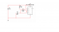
So I have made a small board with the tlc555 timer chip on it.the output from pin 3 as measured to ground produces a sawtooth waveform not a square wave as I measured with my osscilloscope.I have attached an image of how my timer is assembled , can some of you point out where the problem may be? Also I can't fully cross out that it might be the osscilloscope itself as it's old and maybe it can't normally reproduce the square wave on the screen I don't know.
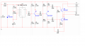
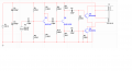
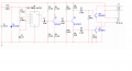
Also I wanted to ask what do you think of my circuit , im planning to use the the 555 timer output to drive a class A amplifier with a C class output stage using two powerful BJT'S to drive the primary of a ferrite core transformer , sort of to make a simple smps. what do you think of the circuit will it perform the way i intend? Multisim shows it should.the bipolar voltage osscillator in the multisim drawing is meant to be the output of my 555 timer, also the output transistors are BUX98A instead of the ones in the drawing because in my multisim database there were no bux98a.
P.S. Just in case someone's worried , I have dealt with eectronics for quite some time, have repaired and built some amplifiers tv's and other gadgets , I have built a simple smps from a chip and sokme mosfets , but I just wanted to experiment with this idea.
Thanks.
So I have made a small board with the tlc555 timer chip on it.the output from pin 3 as measured to ground produces a sawtooth waveform not a square wave as I measured with my osscilloscope.I have attached an image of how my timer is assembled , can some of you point out where the problem may be? Also I can't fully cross out that it might be the osscilloscope itself as it's old and maybe it can't normally reproduce the square wave on the screen I don't know.
Also I wanted to ask what do you think of my circuit , im planning to use the the 555 timer output to drive a class A amplifier with a C class output stage using two powerful BJT'S to drive the primary of a ferrite core transformer , sort of to make a simple smps. what do you think of the circuit will it perform the way i intend? Multisim shows it should.the bipolar voltage osscillator in the multisim drawing is meant to be the output of my 555 timer, also the output transistors are BUX98A instead of the ones in the drawing because in my multisim database there were no bux98a.
P.S. Just in case someone's worried , I have dealt with eectronics for quite some time, have repaired and built some amplifiers tv's and other gadgets , I have built a simple smps from a chip and sokme mosfets , but I just wanted to experiment with this idea.
Thanks.
Attachments
-
 29.6 KB Views: 44
 -
 51.6 KB Views: 43
")