Facebook
 Google
 GitHub
 Linkedin
Hi,
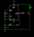
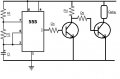
I have attached the circuit diagram of my setup.
I want to drive the relay for about 3 seconds after about every half an hour, as per one of the online calculators I have selected components:
+VCC = 9V
R1 = 470K
R2/R4/R5 = 1K
R3 = 2.2K
C1 = 4700mf
Both Transistors are BC547 NPN Transistors.
Now, after I power the circuit, as soon as the IC triggers for the 1st time, it overheats and gets damaged. does anyone know why it happens?
Attachments
-
 24.1 KB Views: 33