555 timer output not producing time delay

Thread Starter

jacbk612

Joined Feb 8, 2017
47
I could not see wwhy the LM317 output was dropping so much on load so I decided It was easier to buld the circuit so I could take reading myself. The only difference was that I used an 820 ohm resistor in place of the 800 ohm in the schematic setting the LM317's output voltage. The nearest motor I could find that took a bit more current than the one that the OP was using initialy showed a resistance of about 8 ohms. The circuit worked straight away without any problems. The LM317 was supplied with 9.0 volts from the bench power supply. It's output was 5.46 volts when the motor was not running dropping to 5.43 when the motor was running. The analog current meter showed a peak reading of about 2.5 amps dropping to 1.4 amps when the motor was up to speed. As the 2.5 amp peak current did not make sense with the initial 8 ohms resistance of the motor I measured it again. It now measured about 1.2 ohms. I assume that the brushes had bedded in as this was the first time this motor had been used. I used a logic level mosfet (FDS8896) as I did not have any suitable bipolar transistors. This difference of switching device would not effect the problem that the OP was having with the 555 resetting due to the output of the LM317 dropping under load. I can only conclude that the OP must have some high resistance connections in his circuit.

Les.
Les, what does OP mean? What is likely cause of high resistance connections:
- breadboard?
- faulty resistors?
- faulty caps.?

Thanks,

Jacques
 

LesJones

Joined Jan 8, 2017
4,509
Hi. OP means original poster. TS is also used which is thread starter. (You in this case.) I did make a change that I forgot about. I used a 1 uF mylar capacitor for decoupling the output of the LM317 as suggested on the data sheet. I would suspect conections on the breadboard or the long connections causing the LM317 to oscillate. I have never used breadboard. I normaly use stripboard. I suggest that you concentrate on the LM317 part of the circuit. The fact that the LM317 tolerated the 2.5 amp starting current of the motor surprised me.

Les.
 

Thread Starter

jacbk612

Joined Feb 8, 2017
47
I could not see wwhy the LM317 output was dropping so much on load so I decided It was easier to buld the circuit so I could take reading myself. The only difference was that I used an 820 ohm resistor in place of the 800 ohm in the schematic setting the LM317's output voltage. The nearest motor I could find that took a bit more current than the one that the OP was using initialy showed a resistance of about 8 ohms. The circuit worked straight away without any problems. The LM317 was supplied with 9.0 volts from the bench power supply. It's output was 5.46 volts when the motor was not running dropping to 5.43 when the motor was running. The analog current meter showed a peak reading of about 2.5 amps dropping to 1.4 amps when the motor was up to speed. As the 2.5 amp peak current did not make sense with the initial 8 ohms resistance of the motor I measured it again. It now measured about 1.2 ohms. I assume that the brushes had bedded in as this was the first time this motor had been used. I used a logic level mosfet (FDS8896) as I did not have any suitable bipolar transistors. This difference of switching device would not effect the problem that the OP was having with the 555 resetting due to the output of the LM317 dropping under load. I can only conclude that the OP must have some high resistance connections in his circuit.

Les.
Les, what does OP mean? What is likely cause of high resistance connections:
- breadboard?
- faulty resistors?
- faulty caps.?

Thanks,

Jacques
 

Thread Starter

jacbk612

Joined Feb 8, 2017
47
Hi. OP means original poster. TS is also used which is thread starter. (You in this case.) I did make a change that I forgot about. I used a 1 uF mylar capacitor for decoupling the output of the LM317 as suggested on the data sheet. I would suspect conections on the breadboard or the long connections causing the LM317 to oscillate. I have never used breadboard. I normaly use stripboard. I suggest that you concentrate on the LM317 part of the circuit. The fact that the LM317 tolerated the 2.5 amp starting current of the motor surprised me.

Les.
Stripboard implies soldering, that's allot of work, thanks for going through all that trouble.

I will give it a shot, not much to loose now.

Jacques
 

Thread Starter

jacbk612

Joined Feb 8, 2017
47
I would like to get a recommendation of where to buy electronic components on-line for delivery to Montreal, Canada. My local electronic supply store has limited stock. Amazon is one of my favorites but if the product is not on Prime then delivery time is quite erratic sometimes up to 2 months and the prices are also very erratic.

Thanks,

Jacques
 

DigiMax

Joined May 17, 2016
8
I don't think that component supply is your problem Jacques. Les has given you a good lead, its associated with the regulated supply i think also , you have to determining why you have such a voltage swing , poor connenection, try hard mounting of the regulator curcuitry seperatly .
Cheers,
 

Thread Starter

jacbk612

Joined Feb 8, 2017
47
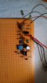
Hello, I have just duplicated the whole breadboard setup on a perforated board using the mosfet IRF530.and the results are the same. So it would seem the breadboard is not in question.
I went back to the breadboard using the mosfet Les selected the FDS8896, I used pin1 for S, pin 4 for G and pin 5 D using the same resistors around the gate, and the results are the same.

Jacques
 

Attachments

Thread Starter

jacbk612

Joined Feb 8, 2017
47
Hello, maybe this should be a separate thread but could anyone recommend a tutorial on how to make a printed circuit board and is there any software out there to help design the board?

Thanks,

Jacques
 

Thread Starter

jacbk612

Joined Feb 8, 2017
47
My circuit operates on a 9V battery and I would like to maximize the battery life. I already have a cmos version of the 555 timer and a mosfet instead of a relay.

I believe someone mentioned that there is a cmos version of the LM317 voltage regulator. I googled it but could find anything. Does anyone have any specifics?

Thanks,

Jacques
 

Thread Starter

jacbk612

Joined Feb 8, 2017
47
Hello, I re-introduced the manual switch to my circuit and when this switch connection is made it starts the timer. Anybody have any idea of what is causing this and how to avoid affecting the timer?

Thanks,

Jacques
 

Thread Starter

jacbk612

Joined Feb 8, 2017
47
Hello, I re-introduced the manual switch to my circuit and when this switch connection is made it starts the timer. Anybody have any idea of what is causing this and how to avoid affecting the timer?

Thanks,

Jacques
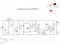
I'll put the schematic here so no one has to look for it.

Also I have managed to measure the current, not sure why I couldn't before. The current is 150 mA at 4.7 V, power is therefore 700 mW.
 

Attachments

Top