 Facebook
 Google
 GitHub
 Linkedin
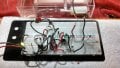
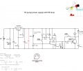
Hello everyone, I am having issues with the 555 timer output, I have included a schematic and a picture of the breadboard. Since there have been a lot of queries on this timer I hope I didn’t miss the solution.
The pin 3 output will not maintain its high pulse for the duration of the pulse that is set by the RC combination on pin 6 & 7. The pump will run if the switch is kept on but there is no time delay.
The purpose of the circuit is to start a 6V small water pump on low level of the tank and then run the pump for a time determined by the RC value on pin 6. Low level is determined by a magnetic switch which for the simulation I have replaced by a manual spring return switch. To avoid the problem of holding the switch to long and not having the output generate the pulse I have put some resistors and capacitor on the switch to generate a low pulse no matter how long the switch is held.
The system works fine with a buzzer substituting for the pump. I have calculated that the pump will draw 240 mW (no info available from the manufacturer). Since the voltage to the pump is 6V that’s 40 mA. The current gain of the transistor is 100 so the current at the base will be 0.4 mA. The voltage at the base of the transistor is 4 (pin3) – 0.7; which means the resistor required at the base is 800 ohms. I suspected that there is not enough power to the pump being suppled by the transistor so I tried changing the resistor on the base to smaller values down to a 100 ohms but this did not work.
Thanks,
Jacques
Attachments
-
 366.1 KB Views: 78
 -
 676.1 KB Views: 116


