
555 timer output not producing time delay

DigiMax

Joined May 17, 2016
8
Hi again,
1. your pump I test circuit, with series10ohm, showed 450ma as expected as dc resistance of pump is similar,
meaning only half the voltage is applied to pump, approx 4.5v, as you found pump won't run.
2. As mentioned earlier by others, pump will require a hi "stall I " to start it, then when spinning will reduce.
3. A voltage source of low impedience is required to start this pump with higher I than you first expected.
4. Since you have purchased these circuit components lets try some short term butchery to get things moving.
5. Move the pump v source away from the regulator, direct to the battery in good order. The driver semiconductor may suffer somewhat but it requires replacement anyway. This will allow your v regulator & timing circuit to a stabler environment.
6.The pump driver will have low gain as mentioned so increase base I.
7. The pump & driver will be over driven but after all this time it may be worth a shot to go past go
8. Try for short term. Good Luck.
 

Thread Starter

jacbk612

Joined Feb 8, 2017
47
I would use a power FET instead of a bipolar. See ebay 361895247878. This will drive any motor at all you have and at 60 cents is probably cheaper than the 2222. Simply connect the FET with the drain to your pump, source to common gnd, and the gate to your 555 output. The other guys are correct in that your battery must supply the required current, which may take at least a set of AA cells in series and maybe larger cells depending on how much running time you want out of the circuit before changing the battery.
The mosfet refered to on ebay is an IRF230, it also has a gate threshold of 2-4V.
 

DigiMax

Joined May 17, 2016
8
To be a little more subtitle with the PN2222A drop a 2 or 3 ohm in series with the pump reducing the I & power
demarned on it for the short term trial.p
 

Thread Starter

jacbk612

Joined Feb 8, 2017
47
To be a little more subtitle with the PN2222A drop a 2 or 3 ohm in series with the pump reducing the I & power
demarned on it for the short term trial.p
Tried it, no help.

Hi again,
1. your pump I test circuit, with series10ohm, showed 450ma as expected as dc resistance of pump is similar,
meaning only half the voltage is applied to pump, approx 4.5v, as you found pump won't run.
2. As mentioned earlier by others, pump will require a hi "stall I " to start it, then when spinning will reduce.
3. A voltage source of low impedience is required to start this pump with higher I than you first expected.
4. Since you have purchased these circuit components lets try some short term butchery to get things moving.
5. Move the pump v source away from the regulator, direct to the battery in good order. The driver semiconductor may suffer somewhat but it requires replacement anyway. This will allow your v regulator & timing circuit to a stabler environment.
6.The pump driver will have low gain as mentioned so increase base I.
7. The pump & driver will be over driven but after all this time it may be worth a shot to go past go
8. Try for short term. Good Luck.
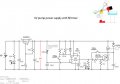
Hi Digimax, thanks for your extensive comments.The pump is rated 3-6V, I hesitate to put more than 6V and I know it operates at 3V.
This morning I will get a mosfet and also a cmos version of the 555 timer,

Jacques
 
Last edited by a moderator:

eetech00

Joined Jun 8, 2013
4,712
Hi Digimax, thanks for your extensive comments.The pump is rated 3-6V, I hesitate to put more than 6V and I know it operates at 3V.
This morning I will get a mosfet and also a cmos version of the 555 timer,

Jacques
Also, the LM317 is not a LDO. Try using a Low DropOut adjustable regulator like an LM2941. That way there will be much less of a voltage drop (0.5v) across the regulator.
 

DigiMax

Joined May 17, 2016
8
There seems something odd about all this- I've used similar circuitry over the years without such problems but think that the weakness is in your driver .I do use f e ts & other heavier bi-polars thou.
I thought it was worth a go since your components were there
I'll keep tab on your progress , good luck
 

Thread Starter

jacbk612

Joined Feb 8, 2017
47
Hello, I have been able to obtain a mosfet IRFZ30 and I have attached the new circuit. The pump does not run, the timer is functioning and the battery does get fairly hot. The store does not have a LM 2941 voltage regulator or the LMC555 cmos timer. Perhaps digikey is the best source but I am reluctant because it always takes a lot of time to ship things to Canada.

Jacques
 

Attachments

DigiMax

Joined May 17, 2016
8
Jacques, from what you observed there is a great load placed on the battery, I hate to suggest, but are you sure the pump polarity correct for it to run??

Is the diode across the pump in the correct polarity, check & above??

Latter thought -how did you determine the correct polarity for that diode,
Markings or multimeter??
In any case check to see if it had failed or replace it.

1. Follow the above,then test
1A. If it fails to work correctly ,go 2.
2. Measure voltage across regulartor
3. Measure voltage which should be 6v.
4. Measure voltage across pump
5. Post checks
 
Last edited by a moderator:

Thread Starter

jacbk612

Joined Feb 8, 2017
47
Jacques, from what you observed there is a great load placed on the battery, I hate to suggest, but are you sure the pump polarity correct for it to run??
Pretty sure, pump runs on the 6V rail.

Is the diode across the pump in the correct polarity, check & above??
The diode is positioned according to the marking for the negative side. This has run before as is with the transistor and a buzzer simulating the pump. What is new now is the buzzer will not run with the mosfet..

Latter thought -how did you determine the correct polarity for that diode,
Markings or multimeter??
In any case check to see if it had failed or replace it.

1. Follow the above,then test
1A. If it fails to work correctly ,go 2.
2. Measure voltage across regulartor
3. Measure voltage which should be 6v.
4. Measure voltage across pump
5. Post checks
Voltage across regulator is 5.5V, voltage across pump zero.
I'm pretty sure I have the mosfet connected properly I am using the layout from a data sheet (image included|).

Jacques

Voltage across regulator is 5.5V, voltage across pump zero.
I'm pretty sure I have the mosfet connected properly I am using the layout from a data sheet (image included|).

Jacques
 

Attachments

Last edited by a moderator:

DigiMax

Joined May 17, 2016
8
Looking at the face of the fet
Left pin 1 is Gate
Middle 2 is Drain
Right. 3 is Source
The tag with the mounting hole is also Drain


You said there is 5.5v across leaving only 3.5v for the pump - from a 9 v battery
1. Check Fet. pinout connection as above. & recheck
1A. If fet was wired incorrectly , it may now have failed
2. Measure V across regulator. Should be about 3v , if so Go 3

3. You have manual run switch for pump test ......does pump run Y/N
4. If all above seem correct test function. Pump runs with delay Y/ N
 

Thread Starter

jacbk612

Joined Feb 8, 2017
47
Ooops. made a mistake. I tested the mosfet according to this procedure https://www.utm.edu/staff/leeb/mostest.htm
and everything went well. While I was doing that I noticed the 10 ohm resistor to the gate was not connected. So now at this point pump does run but affects the timer output stopping the time pulse, buzzer replacing pump works and the timer pulse is maintained. Seems like I'm in the same situation as with the transistor. Voltage at timer pin 3 is 4.1, voltage on regulated rail is 5.1V, voltage while pump running is 4.3V.

Jacques.
 

DigiMax

Joined May 17, 2016
8
Oops Above, you said there is 5.5v across Regulater ............

Try the largest electrylectic capacitor you have across the regulated rails =>10v rating
Impulses on these rails when switching my be reflecting back into the timer.

3am here , good night
 
Last edited by a moderator:

Thread Starter

jacbk612

Joined Feb 8, 2017
47
Try the largest electrylectic capacitor you have across the regulated rails =>10v rating
Impulses on these rails when switching my be reflecting back into the timer.
I've just tried a 220 microF cap., no difference
goodnight

I still think the problem is caused by the lack of a good power supply. Try running it from a car battery.

Les.
Hi Les, I have a large 12V battery, about the quarter of the size of a car battery, no luck.

Jacques

I'm beginning to think that I need an oscilloscope to solve this problem, although it seems like a big challenge for a newbie.

I can get a Tektronix 2213A analog for $200 on kijiji, does such a scope make sense for this project?

Jacques
 
Last edited by a moderator:

LesJones

Joined Jan 8, 2017
4,509
There are problems that you have found that you have not yet solved. In post #63 you say the 6 volts rail (Which I calculate should be 5.42 from the resistor values.) drops from 5.1 volts to 4.3 volts with the load from the pump. The regulator output should not drop that much. The data sheet I have recommends a 1 uF capacitor on the output of the LM317 (Which should be connected as close to it's output as possible.) This may not be the cause of this problem but it is worth trying. The dropout voltage at 25Deg. C and 1.0 amps is about 2.4 volts for the LM317 so you need to ensure that it's input voltage to it does not drop below 8.4 volts. Have you measured this with the pump running ? There are things you can still do without an oscilloscope.

Les.
 

Thread Starter

jacbk612

Joined Feb 8, 2017
47
Ok, I can get a 1 uF capacitor later. Here are some of the readings I get:

8.6V measured at battery off circuit
8.5V measured at battery in the circuit
4.8 V at pump with timer LED on (forced on with switch)
5.2 volt at pump at 6V rail
 

LesJones

Joined Jan 8, 2017
4,509
I could not see wwhy the LM317 output was dropping so much on load so I decided It was easier to buld the circuit so I could take reading myself. The only difference was that I used an 820 ohm resistor in place of the 800 ohm in the schematic setting the LM317's output voltage. The nearest motor I could find that took a bit more current than the one that the OP was using initialy showed a resistance of about 8 ohms. The circuit worked straight away without any problems. The LM317 was supplied with 9.0 volts from the bench power supply. It's output was 5.46 volts when the motor was not running dropping to 5.43 when the motor was running. The analog current meter showed a peak reading of about 2.5 amps dropping to 1.4 amps when the motor was up to speed. As the 2.5 amp peak current did not make sense with the initial 8 ohms resistance of the motor I measured it again. It now measured about 1.2 ohms. I assume that the brushes had bedded in as this was the first time this motor had been used. I used a logic level mosfet (FDS8896) as I did not have any suitable bipolar transistors. This difference of switching device would not effect the problem that the OP was having with the 555 resetting due to the output of the LM317 dropping under load. I can only conclude that the OP must have some high resistance connections in his circuit.

Les.
 

hp1729

Joined Nov 23, 2015
2,304
Just going to back up a few threads here. I can't measure the current while the pump is running, it seems the ammeter affects the circuit. My terminology is probably not right I'm a mechanical engineer and struggling with DIY tutorials, ect. However, I can measure the resistance which is about 10 ohms, which means that with 6V the current will be 600 mA. I'm going to try to lower the resistance to the base to see if I can boost the current to the motor.
Your voltage regulator can only handle 100 mA, maybe 150 mA.
OOPS, I stand corrected, 500 mA on the TO-39 case.
 
Last edited:

Thread Starter

jacbk612

Joined Feb 8, 2017
47
There are problems that you have found that you have not yet solved. In post #63 you say the 6 volts rail (Which I calculate should be 5.42 from the resistor values.) drops from 5.1 volts to 4.3 volts with the load from the pump. The regulator output should not drop that much. The data sheet I have recommends a 1 uF capacitor on the output of the LM317 (Which should be connected as close to it's output as possible.) This may not be the cause of this problem but it is worth trying. The dropout voltage at 25Deg. C and 1.0 amps is about 2.4 volts for the LM317 so you need to ensure that it's input voltage to it does not drop below 8.4 volts. Have you measured this with the pump running ? There are things you can still do without an oscilloscope.

Les.
Tried a 1uF capacitor on the output of the LM317 with no success.
 
Top





