555 timer output not producing time delay

LesJones

Joined Jan 8, 2017
4,509
Can you monitor the voltage on the 6 volt rail when the pump is forced to run with the manual switch ? Also can you disconnect the base resistor from transistor then press the button to start the timing sequence and while watching the LED press the manual switch. Does the LED go out as soon as the manual switch is pressed ?

Les.
 

Thread Starter

jacbk612

Joined Feb 8, 2017
47
Can you monitor the voltage on the 6 volt rail when the pump is forced to run with the manual switch ? Also can you disconnect the base resistor from transistor then press the button to start the timing sequence and while watching the LED press the manual switch. Does the LED go out as soon as the manual switch is pressed ?

Les.
Hi Les,
1st part
the pump supply voltage is 5.5 (battery is getting low) and the pump voltage is 4.8

2nd part
with the pump connected and transistor base disconnected, timing sequence starts, pin 3 LED turns on, when manual switch is pressed pump starts LED at pin 3 turns off.

Jacques
 

LesJones

Joined Jan 8, 2017
4,509
It looks like the current taken by the pump drops the power supply enough to reset the 555. Try it with a more stable power supply.

Les.
 

eetech00

Joined Jun 8, 2013
4,712
Hi
With the LM317 programming resistor set to 800 ohms, output will be about 5.2v.

For 6v output, the LM317 programming resistor should be about 910 ohms, so change 800 ohm resistor 910 ohms,
or, change 800 ohm resistor to 750 ohm resistor with 250 ohm pot in series and adjust output to 6v.

Also change base resistor to 910 ohms. That will provide about 4mA base current.
 

GopherT

Joined Nov 23, 2012
8,009
Connect the 555 and all timing components associated with 555 to the battery (left of the LM317). (it can handle 15 to 18 volts). Connect the output of 555 to the transistor that is controlled by the 6 volts.

Also make sure the LM317 has a minimum load of 5 mA (or whatever your DATASHEET says it should be).

Also, use two 9v batteries in parallel to keep the current supply high enough.
 

Thread Starter

jacbk612

Joined Feb 8, 2017
47
Hi
With the LM317 programming resistor set to 800 ohms, output will be about 5.2v.

For 6v output, the LM317 programming resistor should be about 910 ohms, so change 800 ohm resistor 910 ohms,
or, change 800 ohm resistor to 750 ohm resistor with 250 ohm pot in series and adjust output to 6v.

Also change base resistor to 910 ohms. That will provide about 4mA base current.
Hi, eetech thanks, but I've pretty much tried all these combinations.

Jacques

Connect the 555 and all timing components associated with 555 to the battery (left of the LM317). (it can handle 15 to 18 volts). Connect the output of 555 to the transistor that is controlled by the 6 volts.

Also make sure the LM317 has a minimum load of 5 mA (or whatever your DATASHEET says it should be).

Also, use two 9v batteries in parallel to keep the current supply high enough.
Hi Gopher, sounds like a good idea but it doesn't help. I'll get another battery tomorrow and put them in parallel.

Jacques

It looks like the current taken by the pump drops the power supply enough to reset the 555. Try it with a more stable power supply.

Les.
Yup, Ill try it with 2 batteries in parallel tomorrow.
 
Last edited by a moderator:

hp1729

Joined Nov 23, 2015
2,304
Hello everyone, I am having issues with the 555 timer output, I have included a schematic and a picture of the breadboard. Since there have been a lot of queries on this timer I hope I didn’t miss the solution.

The pin 3 output will not maintain its high pulse for the duration of the pulse that is set by the RC combination on pin 6 & 7. The pump will run if the switch is kept on but there is no time delay.

The purpose of the circuit is to start a 6V small water pump on low level of the tank and then run the pump for a time determined by the RC value on pin 6. Low level is determined by a magnetic switch which for the simulation I have replaced by a manual spring return switch. To avoid the problem of holding the switch to long and not having the output generate the pulse I have put some resistors and capacitor on the switch to generate a low pulse no matter how long the switch is held.

The system works fine with a buzzer substituting for the pump. I have calculated that the pump will draw 240 mW (no info available from the manufacturer). Since the voltage to the pump is 6V that’s 40 mA. The current gain of the transistor is 100 so the current at the base will be 0.4 mA. The voltage at the base of the transistor is 4 (pin3) – 0.7; which means the resistor required at the base is 800 ohms. I suspected that there is not enough power to the pump being suppled by the transistor so I tried changing the resistor on the base to smaller values down to a 100 ohms but this did not work.

Thanks,

Jacques
It sounds like when the motor turns on the +6 V line is dragged down. Much more than 40 mA. If you amp meter doesn't work try putting a small resistor in series with the motor and turning it on by the switch. 5 to 10 ohms, or so. LM317 is a 100 mA version? The motor might be drawing more than that.
 

eetech00

Joined Jun 8, 2013
4,712
Hi, eetech thanks, but I've pretty much tried all these combinations.

Jacques
Hi

Um...this isn't something to "try"....its a requirement for the circuit to work at 6v.

HP makes a good point, that pump is probably going to draw about 200-400mA. Are you using the 1.5 amp version of the LM317?
 

DigiMax

Joined May 17, 2016
8
Earlier you claimed it worked satisfactory with a buzzer. Low I. That suggests much higher I is being drawn by the pump.
1. My first approach would be,as previously suggested, find out the actual I drawn by the pump with a low value R in series with it, across a firm 6v volt supply & measure the V across R then V/R = I .
2. If it's, say around 400ma the transistor Gain would be low & the Emitter Collector voltage drop may be as much as 1.5v creating havoc in turning the pump shaft.
3. Replace pump driver with better emitter/collector characteristics.
3. No extra battery needed.
 

Thread Starter

jacbk612

Joined Feb 8, 2017
47
Hi

Um...this isn't something to "try"....its a requirement for the circuit to work at 6v.

HP makes a good point, that pump is probably going to draw about 200-400mA. Are you using the 1.5 amp version of the LM317?
Ah, didn't know there was a 1.5 A version of the LM317, I will check.

Yup, Ill try it with 2 batteries in parallel tomorrow.
Just tried it with 2 fresh batteries, no luck.

Ah, didn't know there was a 1.5 A version of the LM317, I will check.
I have the LM317T which is rated 1.5A output.

Earlier you claimed it worked satisfactory with a buzzer. Low I. That suggests much higher I is being drawn by the pump.
1. My first approach would be,as previously suggested, find out the actual I drawn by the pump with a low value R in series with it, across a firm 6v volt supply & measure the V across R then V/R = I .
2. If it's, say around 400ma the transistor Gain would be low & the Emitter Collector voltage drop may be as much as 1.5v creating havoc in turning the pump shaft.
3. Replace pump driver with better emitter/collector characteristics.
3. No extra battery needed.
Hello Digimax, I have used a 10 ohm resistor in series with the pump followed by the ammeter. The pump will not run but I do measure a current of 450 mA, not sure if that is meaningful.

What would you suggest as another transistor?

Jacques
 
Last edited by a moderator:

ronsoy2

Joined Sep 25, 2013
71
I would use a power FET instead of a bipolar. See ebay 361895247878. This will drive any motor at all you have and at 60 cents is probably cheaper than the 2222. Simply connect the FET with the drain to your pump, source to common gnd, and the gate to your 555 output. The other guys are correct in that your battery must supply the required current, which may take at least a set of AA cells in series and maybe larger cells depending on how much running time you want out of the circuit before changing the battery.
 

David Pate

Joined Oct 29, 2013
25
If you are drawing 450mA and the pump still does not run, then there is a strong indication. You need to remove the resistor and measure the pump current when it is running. The initial 40mA you calculated is the additional load on the pump to move the water, not the current for the pump to run while dry. Starting amps can be 4 to 6 times the running current for a motor; think of a motor as a full short circuit, limited only by the resistance of the wire in the windings, until the motor starts to spin.
Try a test where the pump runs off of your second 9V cell while the original battery & circuit runs the timer circuit. That is, split the supplies but keep a common ground.
 

Thread Starter

jacbk612

Joined Feb 8, 2017
47
I would use a power FET instead of a bipolar. See ebay 361895247878. This will drive any motor at all you have and at 60 cents is probably cheaper than the 2222. Simply connect the FET with the drain to your pump, source to common gnd, and the gate to your 555 output. The other guys are correct in that your battery must supply the required current, which may take at least a set of AA cells in series and maybe larger cells depending on how much running time you want out of the circuit before changing the battery.
This is what's available at my local electronics supply store: https://addison-electronique.com/searchanise/result?q=irfz30
Will this do?

Jacques
 

Thread Starter

jacbk612

Joined Feb 8, 2017
47
This is what's available at my local electronics supply store: https://addison-electronique.com/searchanise/result?q=irfz30
Will this do?

Jacques
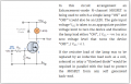
I have been searching the web to understand mosfet's and I have not found a comprehensive article that explains the sizing of the input resistors to the gate. Can someone recommend an article and what the size of the Rin and Rgs resistors should be. I have attached a sketch.

Jacques
 

Attachments

Plamen

Joined Mar 29, 2015
111
You've already proved the timer works in your first post, by substitution of the pump for the buzzer....

So the problem lies with the psu not giving enough current smoothing, i would replace the transistor for a relay, and put a series diode on the 555 pins4,8 supply and 470uF cap, that will stop the re-triggering.
Patkan:
2N2222 is too weak for 600 mA inrush current. Better to use MOSFET - that way there would be no load on 555.
The motor driver can be tested alone. The current could be evaluated by the voltage drop across small resistor in series (say 1R).
 
Just a thought, but it might be a decoupling issue. The regular 555 is very noisy. Is this a CMOS 555? They are quieter than the bipolar ones. Try placing a 1000uF cap in parallel to the 555 very close to the chip and see if that helps.
 
Top