555 timer monostable troubleshooting

Thread Starter

Yuseph

Joined Jun 8, 2020
49
20200606_225909.jpg
15916459039421428215143061458120.jpg
Yo whats up. Im new here.
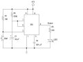
I have this exercice from the book electronics for dummies. I followed the schematic properly. But the led just light up and go off instantly. Not holding 5 secs like its supposed to. Any idea ?
 

Attachments

dl324

Joined Mar 30, 2015
16,845
Welcome to AAC!

Check the connections on the timing elements.

As shown, your circuit won't do anything. There's no ground connection to whatever you're using for a power source.

If you're going to use connection dots, you should use them consistently and put one where pin 7 connects to the timing RC. If it came from the book, shame on them.

Relevant portion of the picture:
clipimage.jpg
 

crutschow

Joined Mar 14, 2008
34,284
Monitor the voltage on pins 7 and 8.
It should rise from 0V towards 9V with a time-constant of 4.7s when the button is pressed, and drop suddenly back to 0V when it reaches about 6V.

Edit: That should be pin 6 and 7.
 
Last edited:

Thread Starter

Yuseph

Joined Jun 8, 2020
49
Monitor the voltage on pins 7 and 8.
It should rise from 0V towards 9V with a time-constant of 4.7s when the button is pressed, and drop suddenly back to 0V when it reaches about 6V.
Pin 8 stays at 8,5v whether its off or on.
Pin7 is off at 0v and raise one sec then drop immediately. Now if i keep the switch pressed pin7 shows 1,65v
 

dl324

Joined Mar 30, 2015
16,845
Pin 8 stays at 8,5v whether its off or on.
As it probably should. The schematic calls for a 9V power supply. Are you using a run down 9V battery? Or are you intentionally using 8.5V?
Pin7 is off at 0v and raise one sec then drop immediately. Now if i keep the switch pressed pin7 shows 1,65v
What "off" mean. Pin 7 is an input.

Does the LED stay on as long as you keep the switch closed?
 

Thread Starter

Yuseph

Joined Jun 8, 2020
49
As it probably should. The schematic calls for a 9V power supply. Are you using a run down 9V battery? Or are you intentionally using 8.5V?
What "off" mean. Pin 7 is an input.

Does the LED stay on as long as you keep the switch closed?
My power supply is a car battery charger. It provides 8,5v sometimes 9v.
By off i mean when the switch is unpressed thats the value i get.
Pin7 switch unpressed = 0v
Pin7 switch pressed = 1,65v
 

dl324

Joined Mar 30, 2015
16,845
My power supply is a car battery charger. It provides 8,5v sometimes 9v.
Weird voltage for a car battery charger. Most batteries are 12V these days and chargers will put out around 13.8V.
By off i mean when the switch is unpressed thats the value i get.
Pin7 switch unpressed = 0v
Pin7 switch pressed = 1,65v
When the circuit is first powered up, pins 6 and 7 should be at 0V because the capacitor is discharged. When you press and release the switch, the capacitor will start charging through R2. When the cap voltage gets to 0.67Vcc, the threshold comparator will toggle the state of the flip flop and the capacitor will be discharged.

Since your switch is directly coupled to the trigger input, you have to release it before the one shot times out. Otherwise, the output will remain HIGH as long as the switch is pressed.
 

Thread Starter

Yuseph

Joined Jun 8, 2020
49
Weird voltage for a car battery charger. Most batteries are 12V these days and chargers will put out around 13.8V.
When the circuit is first powered up, pins 6 and 7 should be at 0V because the capacitor is discharged. When you press and release the switch, the capacitor will start charging through R2. When the cap voltage gets to 0.67Vcc, the threshold comparator will toggle the state of the flip flop and the capacitor will be discharged.

Since your switch is directly coupled to the trigger input, you have to release it before the one shot times out. Otherwise, the output will remain HIGH as long as the switch is pressed.
Its an 80s charger. It delivers 4 outputs. 6v 9v 12v 15v.
Look pins 6 and 7 are at 0v. When i close the switch pin7 value goes up a fraction of a second then drop back. Current doesnt last
 

dl324

Joined Mar 30, 2015
16,845
When i close the switch pin7 value goes up a fraction of a second then drop back. Current doesnt last
Does the LED stay on as long as you have the switch closed? If it doesn't, the chip may be defective. Where did you acquire it? Has it been previously abused?
 

dl324

Joined Mar 30, 2015
16,845
It stays on yes. The chip is fine. Im sure of that
Press and release the switch, then measure the voltage on the timing cap. If it doesn't start charging and continue to charge until the voltage is 0.67Vcc, verify that the capacitor and resistor connections are good.
 

JohnInTX

Joined Jun 26, 2012
4,787
My power supply is a car battery charger. It provides 8,5v sometimes 9v.
Does the car battery charger have a filtered output? Many rely on the connected battery-under-charge to provide the filtering of the rectified output. If it isn’t, your circuit will experience the rectified AC output. Try adding 100 uF across the supply and set the ‘charger’ to the 6V setting.
 

Thread Starter

Yuseph

Joined Jun 8, 2020
49
Not sure its useful but when i maintain then switch closed cap raise at 1,6v the same value as pin6 and pin7
 

dl324

Joined Mar 30, 2015
16,845
Not sure its useful but when i maintain then switch closed cap raise at 1,6v the same value as pin6 and pin7
The quality of your power supply and wiring are being questioned. Have you put a filter cap across the power supply?
 

Thread Starter

Yuseph

Joined Jun 8, 2020
49
Does the car battery charger have a filtered output? Many rely on the connected battery-under-charge to provide the filtering of the rectified output. If it isn’t, your circuit will experience the rectified AC output. Try adding 100 uF across the supply and set the ‘charger’ to the 6V setting.
Wow bro bro bro.. bro !!!
Of all the verifications i made so far, i never thought the problem could be because of the charger being incompletely filtered. I placed a 100uF cap in parallel and boom a solid 5 sec light. The multimeter did monitor shacking AC values. Dammit you re quicker than all the facebook forum amateurs and french forum electronicians combined in here. I can move on to astable now
 

dl324

Joined Mar 30, 2015
16,845
Wow bro bro bro.. bro !!!
Of all the verifications i made so far, i never thought the problem could be because of the charger being incompletely filtered. I placed a 100uF cap in parallel and boom a solid 5 sec light. The multimeter did monitor shacking AC values. Dammit you re quicker than all the facebook forum amateurs and french forum electronicians combined in here. I can move on to astable now
Do yourself a favor and start using a better power supply. Surely you have a bunch of USB chargers laying around.

Most experiments with 555 timers won't be very dependent on supply voltage because it's ratios of Vcc that are used. At/below 0.33Vcc to trigger and at/above 0.67Vcc to reset.
 
Top