 Facebook
 Google
 GitHub
 Linkedin
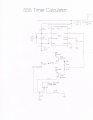
I just can not make these timers work after soldering. They work perfectly on a bread board but once soldered, the timing is erratic. I use a socket for the timer so I don't over heat the timer. I inserted both the LMC555 and the LM555 with identical results. I check each solder line with the meters diode setting. If the buzzer even stutters a little, I unsolder and re-solder the area. I check neighboring solder lines to make sure there is no cross connections.
I am using Bourns #3296-3/8" square trimpots for R1 and R2. I set the resistance before soldering, and leave the prongs long to allow measurements after but once soldered, I can't get the same resistance readings. The readings I get pretty much match the pulse rate I get which is incorrect. I removed the pots and replaced them with fixed resistors with the same results. Even the soldered diode from R1 to C1 was giving a reading of 18K ohms regardless of which side the + and - probes were positioned on it, (how is that even possible ?).
For testing purposes, I have an LED at the discharge of both transistors for visual confirmation of the pulse rate. The pulse rate does not have to be exact but it has to be in the same ball park. Any input would be greatly appreciated .
Attachments
-
 65.2 KB Views: 17


