555 Timer Circuit to set time for 15 seconds with 2 second intervals

crutschow

Joined Mar 14, 2008
38,539
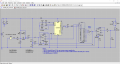
Here's a circuit using the CD4060 as Albert suggested.
With proper selection of the oscillator frequency, only one additional AND gate is required to generate the three one-shot periods.

You operate it in the one-shot mode ( you can leave the relay out if you don't need it).

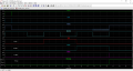
If you configure the oscillator to operate with a 6.85 Hz frequency (C3=200nF) then the Q12 output will give a 5 min. pulse, the Q13 output will give a 10 min. pulse, and the output of a 2-input AND gate connected to Q12 and Q13 will give a 15 min. pulse.

The desired output is selected by a SP3T switch go to D1 for the desired pulse width.
 
Last edited:

Bernard

Joined Aug 7, 2008
5,784
The 555 is still good for 15 min. Need a low leakage 1000 uF cap., greater than 10 M ohm.; 1 M pot in series with 1 k. I have gone to 2.5 hours with a very low leakage 10000 uF cap.
Tolerances have not ben given yet.
 

MrChips

Joined Oct 2, 2009
34,866
It is not a good idea to use electrolytic capacitors as timing elements if you want repeatable results. It would be preferable to go to a higher clock frequency and then use binary dividers to get the desired output frequencies.

If you want a timer with switch selected time intervals you can use a pair of thumbwheel switches and two presetable BCD down counters to give timer delays from 00-99 seconds.

Been there, done it, for a darkroom timer.
 

eetech00

Joined Jun 8, 2013
4,709
Hi

Here's another version using CD4060.

I'm using the CD4060 as a clock with a 5 minute period. I'm not sure of the state the 4060 begins running but I think it starts low and goes high at 50% of the period. That's the reason for the edge detector so that may not be needed. Guess I have to check this on the bench.

Anyway..The circuit is shown for a 15 min cycle, so in operation, the user would use a rotary switch to select the "long" time and then presses the button. This releases the timer to run which triggers the 4017 at the trailing edge of each 5 min period. At the end of the 3rd period (15minutes), Q3 of the 4017 goes high which sets Q of FF U2B high.Q3 also causes FF U2A to reset, stopping the timer via its reset pin. If the user presses the button again, the timing cycle starts over. If the user presses the button during the timing cycle, the cycle starts over.

See attached.

eT

Edit:

Updated schematic.
CD4060 timer runs at 50% duty cycle and begins in low state.
Also changed timing cap to 5uF NP and moved timer output connection to Q7.
Removed edge detect circuit.
 

Attachments

Last edited:
Top