555 Timer Chip LongWave transmitter not working anymore

Thread Starter

ExpL0siV3Man79

Joined Jun 4, 2018
93
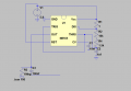
I recently made a 555 timer oscillator that produces a pulse and with the help of a capacitor and a resistor the pulse becomes a square wave...
My radio can receive LongWave transmissions . The transmitter worked for half an hour with crystal clear sound transmission but then stopped and never worked again...I made the circuit again with different parts(same values) , changed batteries ,but it didnt work . Here is a schematic , hope it helps . Note : There is no 10kOhm resistor...It is a 10kOhm potentiometer ! Please help me find a solution . I cant understand why this happens . It worked perfectly and now I cant even detect it...
 

Attachments

MrChips

Joined Oct 2, 2009
34,628
You can create a 555-timer circuit to produce close to 50% duty cycle wave.
R1 and R3 with those values is not the way to do it.
What frequency square wave do you need?
 

Thread Starter

ExpL0siV3Man79

Joined Jun 4, 2018
93
Why I cant use these values ? I added R3 because I needed to add the negative 2.5V . In the falstad simulator it works . Also when I make the frequency too low about 1Hz I can detect that it works with my multimeter . I with the current resistor - cap values the frequency range is from 60kHz to 470kHz . My radio can receive from 150kHz to 350kHz . I dont want a specific frequency . I want many:/
 

sghioto

Joined Dec 31, 2017
8,633
On the schematic R1 is listed at 1 ohm is that correct? Another way is to remove R1 and connect to the output pin 3. This will provide a square wave with a 50% duty cycle.
SG
EEE 555 Long Wave generator.PNG
 
Last edited:

sghioto

Joined Dec 31, 2017
8,633
You might have damaged the chip! Pin 7 is the collector of the internal discharge transistor. When pin 7 goes low with R1 at 1ohm you are trying to force 5.8 amps through the transistor which is rated at 200 ma....not good!:eek:. Change R1 to 1K .
SG
 

Thread Starter

ExpL0siV3Man79

Joined Jun 4, 2018
93
A really long piece of wire around 4 to 3 meters . Also I connect the + of an audio jack , the - goes to ground . I use to connect the + between cap3 and R3 , also the antenna was connected there . The thing is that the C3 and R3 would add the -2.5 volts and forming the final square wave . How can a pulse with only 0 - 5 volts transmit info wirelessly?
 
Last edited:

pyroartist

Joined Oct 9, 2015
131
So where is your audio input connected now that it is working? Is it connected to the open end of C1?
This is a really strange circuit. Like Sghioto said, the 555 normally outputs square waves but at that frequency the capacitance of the long wire antenna is rounding off the square corners of the wave so it becomes more like a sine wave.
 

pyroartist

Joined Oct 9, 2015
131
OK, so my best guess as to how this circuit works is that you are Amplitude Modulating the output (pin 3) by drawing it down, or letting it rise by means of applying an external AC voltage (the audio signal). Anyone agree?
 
Top