Facebook
 Google
 GitHub
 Linkedin
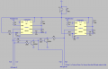
Hi. I am trying to make a circuit that will detect forward and backward motion. It will use two 555 timers, 2 laser sensors, and 2 transistors. This is the way it will work:
If Timer 1 is triggered first, it will output a positive charge to AND gate #1 and AND gate #2. It will also hold the second timer's output low on AND gate #1. Once Timer 2 is activated, it will output a positive charge on AND gate #2. So AND gate #1 is (High, Low) and AND gate #2 is (High, High). So AND gate #2 will output a positive charge. (If timer 2 is activated first while timer 1 is activated afterwards, then AND gate #1 will be High). I use the 2 transistors to sink the current on one terminal of each AND gate.
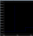
The problem is when I try to simulate it in Ltspice transistor spikes on the collector and base of both transistors. The spikes only occur when the second timer is triggered (not the first). Can you get transistor voltage spikes if you apply voltage to the base while the collector is grounded?
Here is my schematic
If Timer 1 is triggered first, it will output a positive charge to AND gate #1 and AND gate #2. It will also hold the second timer's output low on AND gate #1. Once Timer 2 is activated, it will output a positive charge on AND gate #2. So AND gate #1 is (High, Low) and AND gate #2 is (High, High). So AND gate #2 will output a positive charge. (If timer 2 is activated first while timer 1 is activated afterwards, then AND gate #1 will be High). I use the 2 transistors to sink the current on one terminal of each AND gate.
The problem is when I try to simulate it in Ltspice transistor spikes on the collector and base of both transistors. The spikes only occur when the second timer is triggered (not the first). Can you get transistor voltage spikes if you apply voltage to the base while the collector is grounded?
Here is my schematic
Attachments
-
3.8 KB Views: 16
Last edited: