555-Timer Alternating Blinking LED Circuit, Issue

Thread Starter

bfaridnia

Joined Nov 4, 2010
20
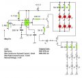
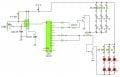
So I am building the following circuit:

Thanks to: http://www.bowdenshobbycircuits.info/555.htm for this schematic.

The circuit is running off of 4.5V, and is working fine in terms of blinking. The only issue I am having is that the top strand, (3pin goes high connected to 2N3053) is much dimmer than the bottom strand (3pin goes low, connected to 2N905). I am using a 1M pot for R2 ( to adjust flash rate) and everything else according to the schematic.

I played with the value of the 220Ohm resistor before 2N3053 transistor (even hooked up a pot to see what the different resistance values gave) and I ended up having it either really dim or not flashing. (the closer i got to it being brighter, the closer i got to the two strands not really alternating.)

I am new to these types of circuits and think it has something to do with a reduced voltage off the 3pin going high. Can someone help troubleshoot this for me?

thanks!
 

eblc1388

Joined Nov 28, 2008
1,542
You have 10 branches of LED, driven by a 2N3053. Let's say each branch takes 20mA so that's a total of 200mA.

Looking at the data sheet of 2N3053, the Vce(sat) at 150mA is 1.4V so it is probably higher in your case with 200mA. So you have about 1.5V drops across the transistor.

Then you have 4.5V-1.5V = 3V for two LEDs and that is too low by any standard, even red leds.

Change to another proper NPN transistor or using 6V will solve your problem. Even using the 2N3053A will give you much better result at 0.4V Vce(sat).
 

Audioguru

Joined Dec 20, 2007
11,248
I betcha you have the collector and emitter of the transistor connected backwards. Then it hardly has any gain like a piece of wire that inverts.

Oh, it is an extremely old 2N3053 transistor. Why not use a better and newer transistor like a TIP31?
 

Thread Starter

bfaridnia

Joined Nov 4, 2010
20
Thanks for the quick replies. I forgot to mention that my local store did not have the 2N3053 and 2N2905's so instead I replaced them with NTE128 and NTE159.

I also only have 6 LEDS per strand. I was thinking the same thing with the resistor placed before the NTE128, I reduced it to 150ohm, nothing, down to 56ohm, and still nothing. I put a POT in instead and used it to adjust to find the right rating. I was only able to get it almost bright but then any more and the other strand went solid (didnt blink)

I would love to use a different resistor (the NTE159 works great) the problem is I am new to this whole thing and the selection so large, that I get confused at what the differences are between them all. (this is why I tried to just follow the schematic, and the recommended replacement NPN and PNP transistors)

for now I have the NTE128 removed from the circuit and just run the NTE159 as a flasher. I would love to have them alternate though. Hope this helps clarify.. Thanks!
 

Audioguru

Joined Dec 20, 2007
11,248
Your circuit with a supply that is only 4.5V will not work with 6 LEDs per strand. If the LEDs are 3.5V blue ones then they need a 24V supply which is too high for a 555 IC.
Please modify the original schematic in Paint program to show us exactly how you have things connected with the supply voltage shown and either show the spec'd forward voltage of the LEDs or their colour.

EDIT: Maybe your LEDs are in parallel instead of in series like the original circuit?
 

Wendy

Joined Mar 24, 2008
23,415
I like eblc1388 analysis. If you read the link I gave you you should know about Vf, the minimum dropping voltage of the LED. You must have a power supply that exceeds that, and the resistor in series with the LED is calculated accordingly. Chapter 1 and 2 cover that in detail.
 

Thread Starter

bfaridnia

Joined Nov 4, 2010
20
I am wiring them in Parallel. The total draw per led is roughly 2.2-2.5V. My power source at 4.5V is enough to supply that to them in parallel (just use up the current faster). Before using this circuit all 12 LEDS were powered off of the 4.5V supply.

LEDS:
I calculated the resistance needed for the LEDs based off of their forward voltage drop, max forward current and total power supply draw. I used the calculator here: http://ledcalc.com to get the values, and came out with 26 or 36ohm. Next up available to me at the store was 56ohm. Each LED is wired, two LEDS with one resistor. I chose that setup to ensure if one set goes, the entire chain stays fine.

Not sure why when the 3pinout goes High its dimmer than low. It could be the V out at Hi is less than 4.5 and thus wont be enough to power but when goes out Low it is. Also could be the LED adding to the forward voltage on the low strand.

Attached is my circuit as it is setup.

Thanks for working with me through this.
 

Attachments

Last edited:

Wendy

Joined Mar 24, 2008
23,415
Here is the thing. Most red LEDs run between 2.2V - 2.5V Vf. If you are using 4.5V you can only have one LED in the chain, not two. 5V would still be too close for 2 LEDs, you really need 6V. You need to know the Vf (forward dropping voltage) of the LED. Please read the article LEDs, 555s, Flashers, and Light Chasers, it is there to get us on the same page, and stop us from going through old material time and time again.

If the Vf of the LED is 2.2, two of them will be 4.4V, and at 4.5 V you simply don't have enough voltage to insert the current limiting resistor. It won't work. If the Vf is 2.5 then 5.0V power supply won't work either. You have a choice, either up the power supply voltage to something usable, or reduce the number of LEDs per chain.
 

Audioguru

Joined Dec 20, 2007
11,248
But the PNP transistor is perfectly turning on two LEDs in series and in series with the same current-limiting resistor and with the same 4.5V power supply.
 

Wendy

Joined Mar 24, 2008
23,415
Not really. Vf is somewhat luck of the draw, if you happen to get a couple of low ones it will work (barely).
 

Thread Starter

bfaridnia

Joined Nov 4, 2010
20
Here is the thing. I see your point ab the resistors. But the stands light up fine and bright when connected straight to power. And the lower stand stays the same brightness when connected in the circuit. If I remove the stands and replace with one led only on both upper and lower points, the same occurs. Hi output is dimmer than low. Which makes me believe it is not the stands. (flipping them also keeps the same issue). I read your links and in terms of the leds I have followed the info. These leds are running 2v and maybe ill lower the 56 to something smaller. But I will still have this issue.

Also, ive tried with blue leds and 150ohm resistor for each and still replicate the issue.
 

SgtWookie

Joined Jul 17, 2007
22,230
I take it that you are using a standard bjt (transistorized) 555 timer?

Or, are you using a CMOS version?

Please specify the exact part number; IE: LM555N, TLC555N, etc. This will help a great deal in nailing down exactly what's wrong.

You were on the right track in one of your prior statements when you were thinking that the pin 3 output did not go as high as it should when high, like when it goes low.

A bjt 555's output can sink up to 200mA when low, and it's output is still pretty close to GND (<0.4v) even when sinking that much current. However when , even under light loads, it doesn't get much closer than Vcc-1.3v, and things just go downhill as the load increases. It can still source up to 200mA, but by then you might be Vcc-1.7v; if your Vcc is only 4.5v, you might be anywhere from 3.1v down to 2.7v when pin 3 is supposed to be high.

For a bjt 555, one way to help the situation is to add a pull-up resistor to the output; connecting pin 3 to Vcc. A 220 to 330 Ohm 1/4W pull-up resistor should help things a good bit.

CMOS 555's (like the TLC555N) are a whole 'nother animal; in general their outputs can sink up to 100mA when low, but only source up to 10mA when high. Their outputs DO go all the way from Vcc to GND; it's just that they are more limited in source and sink current. This is a problem when you are trying to drive a heavy load, like a power transistor's base.

The "fix" for the CMOS timer is a bit different; you use a voltage follower/buffer, consisting of an NPN and PNP transistor with their emitters tied together as the output, bases tied together on pin 3, and the NPN collector to Vcc and the PNP's collector to GND. This way, the emitters "follow" the voltage that's on the bases, and the output current of the CMOS timer is amplified by the gain of the transistors. There is a small disadvantage, as the output at the emitters is no longer rail-to-rail; it only comes within about 0.7v of the rail.
 

Thread Starter

bfaridnia

Joined Nov 4, 2010
20
Great This is what was bothering me in troubleshooting. I'm using the TLC555/TLC555CP LinCMOS Timer (8-Pin DIP) from RS.
 

Wendy

Joined Mar 24, 2008
23,415
You are using transistors to drive the LEDs. The transistors are simple switches. You lucked into the right type of 555 to turn both sides off the way you want to, though I suspect you may be fighting the fact that a CMOS 555 has much more drive on one side than the other.

Have you see these? It is a set of projects, all of which revolve around 555's and LEDs (the LEDs tend to show what is happening).

The 555 Projects

Many of them flash an LED with as little as 3V using a CMOS 555 timer off of 2 AAA cells, for over 1 month, some much longer.

I will be glad to draw you up a schematic that will work, using your CMOS 555 and 4.5 volts, driving as many LEDs as you want. There will not be 2 per chain though, and you will be restricted to red LEDs.

For other colors you need more power supply voltage. Blue and white LEDs need around 3.6 volts to turn on. All LEDs are current devices, but they need their minimum Vf.

Side note, get in the habit of measuring Vf yourself. It is easy to do, and does make a difference, especially when applications are on the edge of not working to spec as yours is, due to variations in tolerances.
 

Audioguru

Joined Dec 20, 2007
11,248
Wait a minute!
The Cmos 555 has plenty of output-low current to turn on the PNP transistor so its LEDs should be almost as bright as when they are tested connected to the 4.5V supply but they are dim. The output-high current from the Cmos 555 to turn on the NPN transistor is much lower but its LEDs are bright.

So either the TLC555 or the PNP transistor is defective. Maybe both are defective since they did not come from a real electronic parts distributor.
 

Thread Starter

bfaridnia

Joined Nov 4, 2010
20
@Audioguru: I am a newb at this stuff but thats what i was thinking too. It is also working fine in my testing software... not sure what is going on.


I will be glad to draw you up a schematic that will work, using your CMOS 555 and 4.5 volts, driving as many LEDs as you want. There will not be 2 per chain though, and you will be restricted to red LEDs.
That would be great. The idea is this is for a riding jacket for my bike. I'm training for the AIDS LifeCycle ride which is a 545mi bike ride from SF to LA. Anything you guys can do to help me with this is greatly appreciated (and considered a donation!)

I checked out the 555 section (blog type) and also was interested in the double flash effect achieved with the CD4017. If I bypass the transistors at the output of the 555 and instead put them on the outputs of say pin 0,2 and 5,7 of the CD4017 chip, could that work (including the PNPs TIP31 or similar). I didnt understand though what the module at the bottom is, that the lines are going to out of the 4017 (LM317T) following this:


For now, I would settle with a single alternating flash between the RED leds. and move to the double flash for my blue ones.

thanks.
 

Audioguru

Joined Dec 20, 2007
11,248
If you are using a TLC555 then please call it a Cmos 555, not a regular 555.

The CD4017 has a fairly low output current when its supply is as low as 3V to 4.5V. Then the transistors will not turn on hard enough to light the LEDs brightly.

Two LEDs in series will not light when the battery runs down to 3.6V or less which happens quickly. 3 cells will make 3.6V for most of their life which is not enough voltage to run the circuit.

Most of your problems are cause by not using enough battery cells so the supply voltage is too low. Use 4 cells or 6 cells.
 

Thread Starter

bfaridnia

Joined Nov 4, 2010
20
Ok. Part of the issue is there are three sets of these circuits on the bike. (1 at the moment) and so I am trying to cut down on the battery load. But It does look like I am trying to power a lot more with a lot less. And sorry about the CMOS-555. Noted for future reference.

Each LED is hardwired with the appropriate resistor for 4.5v, I will have to rewire the strands if I step up to 6v? or could I toss a resistor before the strand that will (when added with the already hardwired one) adjust for 6v?
 
Top