555 monostable timer, pulsed LED and buzzer motor

AlbertHall

Joined Jun 4, 2014
12,628
True, but there's nothing automatically wrong with that since R5 is not needed to protect the Q1 base.

If the intent of R5 is to set a minimum ramp time, 220 ohms is kinda small. That's a time constant of around 50 ms*, and the LEDs go from full dark to full bright in only a portion of that.

* The time constant calculates out to 48.4 ms, but Q1's base current steals away some of the charging current, increasing the ramp time.

ak
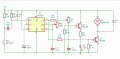
With RV2 at zero, the R5/C2 time constant is applied to the motor drive so the motor speed will ramp rather switch.
I don't know what the effect of 220uF on the Q pin of the '555 will have on the chip function.
 

Thread Starter

dMEK

Joined Apr 4, 2019
16
This was the circuit I ended up with - it functions as desired - thanks for all the advice

I had to add R7 so that C2 would drain a bit faster for a better ramp down time


upload_2019-4-15_13-39-28.png
 

Thread Starter

dMEK

Joined Apr 4, 2019
16
Okay - I had to remove R6 to get the timed pulse to operate correctly

finally I would like the output to only give a signal for the length of the pulse, even if SW1 is held down - 1 pulse per trigger
Is it possible to do this with only analog components?
 

Thread Starter

dMEK

Joined Apr 4, 2019
16
I found this circuit for a differentiating input to generate a short pulse rather than continuous signal from the switch - this should solve the issue?


AnalogKid

Joined Aug 1, 2013
12,147
All the parts are in the right places.

HOWEVER - if RV1 is fully clockwise, U1 will eventually fail. To be clear, that is assuming RV1 is not ultra-cheap. Cheap pots do not go to zero resistance when the wiper is against one of the stops, and that might save your chip. But don't confuse luck with good design.

ak
 

Thread Starter

dMEK

Joined Apr 4, 2019
16
Okay - new question - I have replaced the switch with a transistor - the collector and emitter on each side of the switch

The base is connected to a conducting plate to work as a capacitive touch pad - I have replaced R1 and R2 with 2M resistors

I am finding the sensitivity to be a bit on the low side, sometimes it works with skin touching the pad, sometimes it doesn't - which one of those two resistor would affect the sensitivity the most? both? and would a higher value make it more sensitive?
 
Last edited:

Thread Starter

dMEK

Joined Apr 4, 2019
16
I am getting the sensitivity I am after without using the transistor and without R2, but without those, the output just stays on so long as there is contact on the touch pad

upload_2019-5-17_17-5-53.png
 

Thread Starter

dMEK

Joined Apr 4, 2019
16
basically the problem I am now having is that I just want it to give a single pulse with each contact with the touchpad, rather than continuously pulsing
 

eetech00

Joined Jun 8, 2013
4,709
Hi

Try this...it should work if you "tap" the pad. If you hold your finger on the pad, probably wont.

upload_2019-5-17_16-4-9.png

The pot adjusts sensitivity.

eT
 
Last edited:

Thread Starter

dMEK

Joined Apr 4, 2019
16
12V DC power supply. The trigger pin needs a very weak pull up to have enough sensitivity for the touch pad to work

It is working fine with a tap, I would like it to latch when you keep your hand on it so it just does a single monostable pulse then stops until you lift and recontact the pad
 

djsfantasi

Joined Apr 11, 2010
9,237
When your finger is held on the touchpad, is the 555 pulsing or just staying on, like you stated in post #31?

The latter makes more sense.

When the 555 is configured as a one shot and the trigger remains on, the output will remain on as you have noted.

What you need is to set the trigger through an edge detector. This will only output one pulse while the trigger input remains set.

This article on AAC shows such a circuit. It might even replace your 555 circuit, if the output pulse length isn’t critical.

F91132E9-0F74-4457-9F14-39F430937E6F.jpeg
 

eetech00

Joined Jun 8, 2013
4,709
12V DC power supply. The trigger pin needs a very weak pull up to have enough sensitivity for the touch pad to work

It is working fine with a tap, I would like it to latch when you keep your hand on it so it just does a single monostable pulse then stops until you lift and recontact the pad
Hi

Ok...try this. I'm assuming the touch switch is open and goes to ground when touched. If not, we'll re-arrange the circuit.
Once again, the pot adjusts sensitivity. If the touch pad is tapped or held pressed, it should trigger the 555 once.

see below.

eT

edit:fixed

upload_2019-5-18_14-6-9.png
 
Last edited:
Top