Facebook
 Google
 GitHub
 Linkedin
I'm building an instrument which includes counting engine revolutions for a period of time (15-30 seconds) at the same time I am counting wheel revolutions.
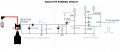
I have an inductive clamp to go over the spark plug wire, and found a circuit which uses some diodes, resistors, and capacitors to get the induced voltage down where it needs to be to trigger an SCR. The SCR feeds a 555 in what I believe is monostable configuration, whose output nominally is a 5V square wave. At least, that is what the circuit diagram shows.
I breadboaded this, hooked it up to a frequency counter (in count mode), and to an old oscilloscope (has tubes inside it) I've pretty much forgotten how to use, and clamped onto a 6 cylinder engine's spark coil wire. This will give three sparks into the distributor per engine revolution. I manually timed the counts on the counter for ~30 seconds, and they seemed about right for what the tachometer showed, so the circuit is working.
However, the trace of the 555's output on the oscilloscope showed a sawtooth wave, and not a square wave. Since the counter counted, I may not need a square wave, but I'd like to know why it wasn't square.
I've attached the circuit, or think I have. The 555 is running on 5V, and what I take to be the timing components are an 18K resistor from Vcc to Discharge (pin 7), and a 0.1microF (100nF) cap from the Input+ (pin 6) to ground. Pins 6 and 7 are also joined.
For what I am doing, the engine won't run over 2,000 rpm, though my expectation is to have it idle at 800-1000 rpm. 1,000 rpm = 16.7 Hz, times 3 = 50 Hz. So the period should be 20ms At 2,000 rpm that would be 10ms. If I have this right, maybe I want a 1ms square wave? Plenty long for a counter to pick up on?
I tried to do the R/C calculations for this, but couldn't deal with fractional exponents or whatnot. I'm a cook book futzer, not an EE or anything like that.
What combination of resistor and capacitor do I want here?
I have an inductive clamp to go over the spark plug wire, and found a circuit which uses some diodes, resistors, and capacitors to get the induced voltage down where it needs to be to trigger an SCR. The SCR feeds a 555 in what I believe is monostable configuration, whose output nominally is a 5V square wave. At least, that is what the circuit diagram shows.
I breadboaded this, hooked it up to a frequency counter (in count mode), and to an old oscilloscope (has tubes inside it) I've pretty much forgotten how to use, and clamped onto a 6 cylinder engine's spark coil wire. This will give three sparks into the distributor per engine revolution. I manually timed the counts on the counter for ~30 seconds, and they seemed about right for what the tachometer showed, so the circuit is working.
However, the trace of the 555's output on the oscilloscope showed a sawtooth wave, and not a square wave. Since the counter counted, I may not need a square wave, but I'd like to know why it wasn't square.
I've attached the circuit, or think I have. The 555 is running on 5V, and what I take to be the timing components are an 18K resistor from Vcc to Discharge (pin 7), and a 0.1microF (100nF) cap from the Input+ (pin 6) to ground. Pins 6 and 7 are also joined.
For what I am doing, the engine won't run over 2,000 rpm, though my expectation is to have it idle at 800-1000 rpm. 1,000 rpm = 16.7 Hz, times 3 = 50 Hz. So the period should be 20ms At 2,000 rpm that would be 10ms. If I have this right, maybe I want a 1ms square wave? Plenty long for a counter to pick up on?
I tried to do the R/C calculations for this, but couldn't deal with fractional exponents or whatnot. I'm a cook book futzer, not an EE or anything like that.
What combination of resistor and capacitor do I want here?
Attachments
-
 22.9 KB Views: 46