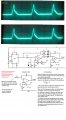
555 Help

tubeguy

Joined Nov 3, 2012
1,157
As tracecom pointed out the transformer is not a good idea or needed.

I'm thinking something like a high current push-pull output stage with feedback through an op-amp.
I've never built something like this but maybe someone has.

You said you need 20 amps current, but what voltage range is required ?
 

Thread Starter

waveguy

Joined Apr 17, 2013
46
Hi tubeguy, I have a 12v power supply for the circuit and a 33 to 60v power supply for the high current side.. If there is a voltage there that will enable someone here to build and expieriment with me that will be fine as the amplitude isnt all that important I just dont want to go over 120 on the primary side.I am only using the small transformer in the circuit as a wave to vary the shape of the waveform. I hope to get the waveform pictured and circuit capable of pulsing the primary of a larger transformer.. probably an old microwave transformer... if we can do that much it would be awsome... lets get the waveform pictured and feed it to the primary of a microwave transformer and the secondary of that into a coil of wire... the coil of wire will be used to create a magnetic field of varing amplitude and current for expieriments at home.
 

shortbus

Joined Sep 30, 2009
10,049
Why wouldn't you just use one of the many sawtooth wave generator circuits that are known to work. Instead of something that "might" work?

And it still doesn't address the cap between the primary leg and ground.
 

tubeguy

Joined Nov 3, 2012
1,157
You seem to be intent on using a transformer for "shaping" your waveform.
Could you please explain why in more detail ??? :)
 

Thread Starter

waveguy

Joined Apr 17, 2013
46
Why wouldn't you just use one of the many sawtooth wave generator circuits that are known to work. Instead of something that "might" work?

And it still doesn't address the cap between the primary leg and ground.
That was the only negative going ramp circuit i could find using a 555 and I dont know why the cap effects the waveform myself.. i was hoping someone here could tell me that...all i know is that varing the value of that cap varries the output waveform characteristicsl.

The only other way we can get the waveform needed would be to combine a sawtooth and a triangle wave.I could not find a constant amplitude triangle wave circuit.I really dont care how we get the waveform just as long as it looks like the one I posted and can get it into an AC waveform.From the looks of my circuit I would love to build it diffrently because for some reason I can not seem to get the waveform needed again.I get close with the transformer but just cant seem to get it right :/
 

Thread Starter

waveguy

Joined Apr 17, 2013
46
You seem to be intent on using a transformer for "shaping" your waveform.
Could you please explain why in more detail ??? :)
well really I would love to find a better way to get the waveform again because alltho the transformer is getting me close again... i cant seem to reproduce it :/ The waveform needed is a "saw triangular waveform " I dont care how its formed as long as its reproducable and stable.
 

shortbus

Joined Sep 30, 2009
10,049
You keep saying AC. You do know that AC has both a positive and negative component to it? The picture of your scope shot just shows a pulsed DC wave form.

As I and others have said, if you share what the final result is, that your after, maybe you could be helped. A magnetic wave in a wire does not help. No one knows what your doing, so how can we help? We are not asking so we can steal your idea, but so we can make sense of what your doing to help you.
 

Thread Starter

waveguy

Joined Apr 17, 2013
46
You keep saying AC. You do know that AC has both a positive and negative component to it? The picture of your scope shot just shows a pulsed DC wave form.

As I and others have said, if you share what the final result is, that your after, maybe you could be helped. A magnetic wave in a wire does not help. No one knows what your doing, so how can we help? We are not asking so we can steal your idea, but so we can make sense of what your doing to help you.
yes im aware of what an AC signal is... thats why I keep saying I need that into an AC signal... i dont care how its done... thats why im here asking for help... ive been working on this nearly 6 weeks and now i just need that waveform back i dont care how its done as long as its as simple as can be and a sturdy circuit.As far as what im doing... lets forget about a magnetic field and just go with ecthing metal, thats what I want to do ... i want to expieriment with the waveform.
 
Last edited:

Thread Starter

waveguy

Joined Apr 17, 2013
46
Are you trying to duplicate the sawtooth-triangle wave from a Moog synthesizer?
yes.
I have read his waveform is a sawtooth on the left and a triangle on the right.I could never find a constant amplitude triangle wave circuit .

I have his schematics and patents and have looked over them but the exact waveform can be found in us patent 4297184. I tried to find a decent link but all i could find was downloads to the pdf.

I was amazed after weeks of tinkering and gettingg the waveform pictured with the circuit posted... however i can not seem to duplicate the results after moving my workstaion off the coffee table to another table.
 
Last edited:

shortbus

Joined Sep 30, 2009
10,049
Again I'm confused? One one hand you are saying a Moog synthesizer(musical instrument?) then you give a patent for etching/anodizing aluminum.

I have a couple of books on oscillators that I'll look at and see if there is anything like this in them. Did you look at all of the reference patents listed in the one you showed? Some times the ones that are referenced will show more of the original concept that that patent is based on. Do you know about freepatentsonline.com ? puts all patents in a searchable data base.
 

timescope

Joined Dec 14, 2011
298
It is possible to derive any waveform if we know what you want.

1. Post a drawing of the waveform that you want showing the amplitude and frequency.

2. Forget about the transformer for now.

3. Note that if you drive a mosfet with a waveform that rises slowly, it will dissipate power and get hot.

Timescope
 

Thread Starter

waveguy

Joined Apr 17, 2013
46
Again I'm confused? One one hand you are saying a Moog synthesizer(musical instrument?) then you give a patent for etching/anodizing aluminum.

I have a couple of books on oscillators that I'll look at and see if there is anything like this in them. Did you look at all of the reference patents listed in the one you showed? Some times the ones that are referenced will show more of the original concept that that patent is based on. Do you know about freepatentsonline.com ? puts all patents in a searchable data base.
Thank you shortbus for looking through your books :) The moog waveform looks just like the one i got on my scope those few days... looking at the patent waveform, the one i actually need is why i keep saying i needed the one i posted into an AC waveform.. I thought if i could create the top half of the waveform which i did... i could put that into a transformer and i would get the AC waveform... im really illiterate to circuits and transformers so I know now putting a waveform into a transformer doesnt actually mean I get the AC waveform I was looking for.
 

Thread Starter

waveguy

Joined Apr 17, 2013
46
It is possible to derive any waveform if we know what you want.

1. Post a drawing of the waveform that you want showing the amplitude and frequency.

2. Forget about the transformer for now.

3. Note that if you drive a mosfet with a waveform that rises slowly, it will dissipate power and get hot.

Timescope
The waveform I need is on page 1... i actually got it for a few days with the circuit posted there as well... The 555 ciruit is working but for some reason every time i hook the gate of the mosfet to the 555 and then the source pin of the FET to ground i loose the 555 signal and get nothing :/ Thank you timescope I hope we can figure this thing out with simple analog parts for now,I would really love to go with a microchip but if we can pull this off with a 555 or some op amps and transistors would be great! The amplitude and frequency isnt going to matter that much as long as the waveform can handle up to 20 amps, it would be REALLY nice if it was variable in amplitude up to 100 volts and in frequency from 1k to 10k or beyond.The waveform actually has a fast rise time and a slow fall tim in 2 stages.The fall time is the key to this waveform.. it must at first fall fast and then half way down or so fall down more slowly .. exactly like the waveform on page 1 of my scope shot.The only thing is we will need an inverted stage or what ever it takes to make that waveform into an AC waveform like the one referanced in the patent i posted.Thanks again for being apart of this !!!
 

shortbus

Joined Sep 30, 2009
10,049
Thank you shortbus for looking through your books :) The moog waveform looks just like the one i got on my scope those few days... looking at the patent waveform, the one i actually need is why i keep saying i needed the one i posted into an AC waveform.. I thought if i could create the top half of the waveform which i did... i could put that into a transformer and i would get the AC waveform... im really illiterate to circuits and transformers so I know now putting a waveform into a transformer doesnt actually mean I get the AC waveform I was looking for.
The wave form from the patent, is from the effect of the etch, if you read it clear through. It is similar to what I'm doing, except mine is a pulsed DC. An EDM is what I'm making. But like the patent the wave form is do to the way the electricity is transferred to the aluminum sheet in the patent.

My guess on why you got the wave on the scope was the 555 was dying internally.

The reason you get nothing when you used a load on the secondary is the very low output current from the 555. When you used the secondary, there was not enough current to magnetize the core. With nothing on the secondary, the primary was acting like a big iron core inductor.

You still haven't stated which your doing, a synth or etching?
 

Thread Starter

waveguy

Joined Apr 17, 2013
46
The wave form from the patent, is from the effect of the etch, if you read it clear through. It is similar to what I'm doing, except mine is a pulsed DC. An EDM is what I'm making. But like the patent the wave form is do to the way the electricity is transferred to the aluminum sheet in the patent.

My guess on why you got the wave on the scope was the 555 was dying internally.

The reason you get nothing when you used a load on the secondary is the very low output current from the 555. When you used the secondary, there was not enough current to magnetize the core. With nothing on the secondary, the primary was acting like a big iron core inductor.

You still haven't stated which your doing, a synth or etching?
Yea I understood the effect of the solution in the etching patent.... i wish i had tools to measure EVERYTHING like the dying 555 when i had the waveform in hopes of being able to replicate the effect.
Even with a very small transistor the 555 cuts out if the emitter or source is connected to ground.... maybe ive almost killed another 555... ill try a new one and see how that goes... is there something im missing to prevent this 555 failure you can think of?
Im actually not doing either etching or the synth... I need the waveform for an energy expieriment.I hope it being an energy expieriment dont diswade yall from being apart of it:/
 

shortbus

Joined Sep 30, 2009
10,049
@Timescope, wow, I'm very, very impressed. Wish I had your knowledge. From one book on oscillators, I was going to suggest using UJT's for this, but your circuit is a better solution.
 
Last edited:

Thread Starter

waveguy

Joined Apr 17, 2013
46
Hey Timescope, most deffinatley interested ! Three slope generator is great ! I hope it works out, I have no idea the skills required to do what you have done but I am most deffinately interested in your circuit !
 

timescope

Joined Dec 14, 2011
298
Hi waveguy,

Im wanting a variable frequency and duty cycle with the circuit as well but even a fixed frequency of around 1286k will work.
I will assume that the waveform you posted is 1.286 kHz and work out the component values.

@shortbus, thanks. I also wish that I had your knowledge. That's why we are here in this great forum.

Timescope
 
Top