555 as timer on delay for high inrush DC motor

Thread Starter

Evera

Joined Oct 10, 2020
4
Hello,

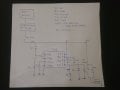
I am trying to design a circuit to drive a 12VDC motor from a 20V battery and I would like to ask for your help.

The application is the following: I want to power a 12V dc motor using a 20 V battery. I used a DC DC converter to convert the 20V from the battery to 12V. The issue I had is the motor has a 30A inrush and 2A steady current, and when I turned on the motor the high inrush current activated the overload protection on my converter.

I decided to use an NTC thermistor to limit the inrush current and then a 555 timer to bypass the thermistor after 1 second. I have a led connected to the 555 output to see when it is ON. The issue I have is when I turn on the switch, the motor starts running through the thermistor, and the 555 turns on and off the output for a few seconds, and then leaves it ON until the switch is turned off. I think in those first few seconds the voltage drops because of the high inrush current (as both 555 and motor are powered from the same 12V). Is there something I can do to avoid this to happen? I don't want to use any programable ICs, I want to do this as simply as possible, but I don't want the 555 output to turn on and off when starting

Also, I tried to do the same with a PTC thermistor (10ohm) instead of a NTC thermistor, but the effect is even worse, the 555 output turns on momentarily and then is off again, so the PTC thermistor is not bypassed for too long, and the cycle repeats every 1 second

Thank you for your help!
 

Attachments

dl324

Joined Mar 30, 2015
16,846
The issue I have is when I turn on the switch, the motor starts running through the thermistor, and the 555 turns on
What are you trying to accomplish with 555? It should turn on after the capacitor charges to 2/3 Vcc.

EDIT: Actually, it'll stay on when the capacitor charges.
 
Last edited:

Thread Starter

Evera

Joined Oct 10, 2020
4
I am trying to activate the relay 1 second after the circuit has turned ON (switch ON) to create a time delay.

The idea is that when I turn the circuit on (switch ON), the motor starts moving receiving power from the NTC thermistor, and after 1 second the 555 timer activates, and the motor gets power from the relay instead (as the relay bypasses the thermistor). I am doing this because with time the thermistor gets really hot, and if I try to turn the circuit on and off again I cannot do it because I have to wait for the thermistor to cool down first

When I turn the switch ON, the 555 output turns ON and OFF several times, and then after a few seconds it turns its output ON as it is supposed to until the main switch is turned OFF. I think this happens because the voltage takes some time to stabilize after the motor turns ON, as this only happens when I start the system the first time (capacitors have to charge?). If I turn the system ON and OFF quickly after it stabilized a first time, I don't find this issue

I put an led at the output (no motor) and the 555 works as intended, for that reason I think motor inrush is affecting the 555 operation
 

Martin_R

Joined Aug 28, 2019
137
Hi, a couple of questions here. Is the power supply up to the job of supplying the initial current? Can you measure the voltage output and see if it drops during the motor on phase?
Second point is the 555 powered from the power supply side of the thermistor or powered from the motor side?
 

Thread Starter

Evera

Joined Oct 10, 2020
4
Hi, a couple of questions here. Is the power supply up to the job of supplying the initial current? Can you measure the voltage output and see if it drops during the motor on phase?
Second point is the 555 powered from the power supply side of the thermistor or powered from the motor side?
Hi!

The circuit is powered by a 3A DC DC converter. It cannot supply the initial 30A inrush current, and for that reason I tried using a thermistor (10 ohm) to limit the initial current, allowing the motor to start. This part of the circuit works. If I don't use a bypass circuit, the motor will run normally, but the thermistor will get too hot to allow me to turn and off the motor continuously

Yes, during the motor on phase the voltage outputs drops from 12V to 7.5V

555 is powered from the power supply side of the thermistor

Thanks!
 

crutschow

Joined Mar 14, 2008
34,285
You likely need to stabilize the power to the 555.

I thought of adding a diode and making C3 larger to stabilize the voltage but, it would require about 10,000μF to allow no more than a 1V drop for a nominal 10mA 555 current during the 1 second motor startup.

So how about powering the 555 (pin 8) directly from the 20V battery?
You could use a 500 ohm resistor and a 12V zener (or a 7812 or LM317 regulator) to generate the 12V for the 555.
C1 would still go to the switched side of S1.
 

Thread Starter

Evera

Joined Oct 10, 2020
4
You likely need to stabilize the power to the 555.

I thought of adding a diode and making C3 larger to stabilize the voltage but, it would require about 10,000μF to allow no more than a 1V drop for a nominal 10mA 555 current during the 1 second motor startup.

So how about powering the 555 (pin 8) directly from the 20V battery?
You could use a 500 ohm resistor and a 12V zener (or a 7812 or LM317 regulator) to generate the 12V for the 555.
C1 would still go to the switched side of S1.
Hi,
I will try what you suggested with the 7812. I'll let you know, thank you!
 

Daniel Sala

Joined May 28, 2015
65
Hi,

Linear soft start could be another option to limit inrush current, but 30A would be a slow effort.

I saw this for capacitative loads, but it might work for the motor as well, probably not...

Iinrush = Cload * Vin/tOn
It's only an e.g. PNP current source or a parallel RC on a PMOS gate to slow down turn-on.
 

jeffl_2

Joined Sep 17, 2013
74
It helps to know a little about your motor. In the absence of other information let's assume it's a common brush type DC motor. In that case all motors at the instant of start (for the first millisecond or so) the current really doesn't build up very quickly because the winding inductance dominates. What happens after that is the rotor starts turning and eventually builds up a back EMF which acts opposite to the input voltage, therefore the "effective" supply voltage is reduced and that's how the current gets reduced to 2 amperes, BUT that situation only maintains so long as the RPM remains fairly high. The "challenge" is usually the brushes, they probably don't take kindly to having to provide 30 amperes for very long, that could be either about carrying the current or about dealing with arcing from the high voltage created when an inductive circuit opens up while carrying a lesser current. What I'm trying to say is there's very little to be gained by "regulating" the motor at 12 volts because it's not really an effective means of "protecting" anything. The best resolution would probably be to provide the motor with a high-current source at whatever voltage is convenient (you don't state whether the 20 volts is a "stiff" source, maybe you need a large capacitor across it) and then you can start "limiting" the supply (limit the voltage to 12 volts, or limit the current some other way) after you have ascertained the motor has reached a minimum "safe" speed (or some "timeout" period is reached and you declare a start fault). OK I know, you don't have a tachometer circuit and don't want to know about them. Look I explained the problem and offered a version of a solution, if you think you (or someone else reading this) has a better answer then go design and build it!
 

splud

Joined Jun 30, 2013
38
It sounds rather like you might need to charge a sufficiently large capacitor bank to 12V (or even 15V or more, because at 30A, it's going to drop off quick) and switch that in briefly to start the motor. The other possibility is actually switching the motor to the 20V in for a moment, and then to the stepped down 12V, but there is a potential you might fry the motor.
 

Deleted member 115935

Joined Dec 31, 1969
0
NTC is a very crude method of limiting inrush current,
but cheap and well used,
why are you needing to bypass the NTC, when its hot , it looses little power

There are many active circuits that might be of help,
the trick is to use a fet to slowly bring up the current to the load,

e.g. https://www.ti.com/lit/slva670

BUT

slowely rising the current to your load might be counter productive.
your motor might need the inrush to get running
rising the current to slow might mean the motor never runs and over heats.

some experiments needed.

but a 555 is over the top for the delay, just use a R/C circuit.
 

Martin_R

Joined Aug 28, 2019
137
Why not connect the thermistor to the 20 volt battery then through a relay to the motor? The relay coil could connect across the motor , and the relay would then select the thermistor via NC contacts and the 12v via the NO contacts during running.
 
Top