Delay cycle timer

Thread Starter

Rick0413

Joined Apr 19, 2025
4
Hi folks,

I am very much a novice regarding electronics so I am not even sure how to ask my question. I am hoping someone will be able to interpret my words below and give me advice.

What I am trying to do: I would like to cycle 120V lights on/off in regular pattern. I build Halloween props and would like to create what is essentially a slow acting strobe function that is unbalanced. Say on for 3 seconds/off for 1 second.

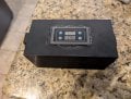
What I found: I found this on Amazon, which would be perfect, if I could get it to work. https://www.icstation.com/110v-120v...-switch-module-265v-display-999h-p-12364.html.

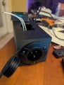
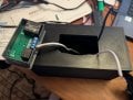
What I have: I have an input side for power and an output side for load. However, I am very unclear with wiring. Not only is it a result of my inexperience, but the nomenclature they are using seems off. They refer to "+" and "-" but how does that relate to hot and neutral? Then they use pin names of GND, VCC (which I thought is for low voltage), S0, and S1. I am unfamiliar with any of those terms. With all of that, I wired my hot and neutral to the GND and VCC pins and the device turned on and functions.

My problem: I get no output voltage. I wired the input to GND and VCC as mentioned above. I then wired my output to SO and S1 with no success. Rather than continue with this, I got my multimeter and started trying different combinations. I get 120V at the input terminals but nothing at the output terminals. I tried testing as if I had a pass through neutral, sort of like you wire a switch in your house. Nothing.

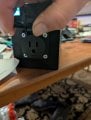
My novice brain thinks it should act like a switch. Input Hot on one pin, output hot on another pin, pass through neutral and some way to turn on the timer device, which I would assume would be low voltage DC, that open and closes the relay. That would make sense to me, but I don't seem to have the inputs required to do that.

So I am stumped. Does anyone have any suggestions?

Rick Romano
 

Attachments

ericgibbs

Joined Jan 29, 2010
21,428
hi Rick,
Welcome to AAC.
That link shows this circuit.
They are using +/- to identify the Line and Neutral supply
E
AC 110V 120V Programmable Digital Cycle Delay Relay Timer Switch Module, AC 85V-265V LED Display 0ms-999h
EG57_ 2825.gif
 

Thread Starter

Rick0413

Joined Apr 19, 2025
4
Thanks for the reply Eric. I am really showing my inexperience but that is still confusing. For want of a better word, this looks like a closed system. If I can ask a couple more questions:

I am assuming that "+" is the line load and "-" is neutral.

In my case, the load is the outlet. In this schematic, it looks like the input power is the gray AC box.

It appears that line load goes to VCC and neutral goes to GND, which does power the unit.

But, then I get confused. It looks like the S0 is the switched port. And it looks like the load side needs power directly from the input side. But why does it appear that the power leg connects directly from the input side to the load device? And it looks like the neutral goes to 2 inputs from the Line load side? And why is there no neutral going to the Load?

In the end, I am unclear how to practically run the wires that I have. The schematic might be showing it but I am not seeing it.

Again, thank you for the help.

Rick
 

LowQCab

Joined Nov 6, 2012
5,101
Switch#0, and Switch#1, markings, are using Computer-Nomenclature,
it could be S#A, and S#B, or S#1, and S#2.
These are simply to indicate the connections to a simple set of Switch-Contacts.
These Switch-Contacts are never connected to
ANYTHING, except for each-other,
and only when the Timer-Circuitry dictates an "ON" condition.

This individual Switch is rated for ~10-Amps of Load at ~120-VAC,
and, ( guessing ), approx. ~3-Amps at ~12-Volts DC, ( if You want to Switch DC ).


Minus and Plus Terminals ..........

These are only for the Power-Supply for the Timer-Electronics.
They must be continuously connected to ~120-VAC, ( or less than ~265-VAC ).
If the ~120-VAC is EVER disconnected from these Terminals,
ALL- Settings will very likely be lost.
In this case, the Timer will very likely revert-back to some "Factory-Default" Settings

The Minus and Plus-Terminals need only a tiny amount
of 120-VAC-Current to operate the internal Timer-Electronic-Circuitry.
Probably less than ~0.1 Amps, or less than ~100-Milli-Amps, of Current.
This means that You can connect over ~100 of these Timers on the same AC-Circuit with no issues.
But the individual-Loads that are being SWITCHED by EACH Timer must not exceed ~10-Amps.

The Minus ( Neutral ), and Plus ( Hot ), Terminals
are not Connected to the 2-Switch-Terminals in any way.

Be very careful in Wiring multiple Minus and Plus Terminals together.
I suggest buying a bunch of Light-Duty, ~6-foot-long, Extension-Cords from Wall-Mart or similar,
then cut-off the Socket-End for direct Wiring to each Timer,
then plug-in each Extension-Cord to a Multi-Outlet-Power-Strip,
which will provide Minus/Plus-Power to all individual Timers.

You may need multiple Multi-Outlet-Power-Strip(s) depending on how many Timers You intend to use.

You should Document the Settings of EACH-TIMER,
on an individual piece of Paper, in the case of a Power-Loss
this will allow You to put everything back to your original settings,
if that's important to You.
After You have entered all of the necessary settings ~5 or ~6 times or more
You may no-longer need the documentation because You
will have learned by this point what all of the Buttons do.
.
.
.
 
Last edited:

Thread Starter

Rick0413

Joined Apr 19, 2025
4
LowQCab, ericgibbs Gentlemen, your kindness in providing insight is greatly appreciated. I thank you for your insights while dealing with a complete novice. With the thoughts provided, I was able to see through the haze of the schematic and wire my little project successfully.

Thank you so much.

Rick
 

LowQCab

Joined Nov 6, 2012
5,101
Have You decided on exactly what type of device(s) You will be Switching ?, ( Lights / Motors etc. ? )

This can help us to understand how to advise You in safely Switching these particular types of Devices.

Be sure to include whether or not they will be used "In-Doors" or "Out-Doors".
.
.
.
 

MisterBill2

Joined Jan 23, 2018
27,402
My thought is rather BAD NEWS!! To me, Vcc means a DC voltage. Of course I did not follow any link to the timer device, but that is what I see.
Probably we could see the relay connections with a photo of the PCB bottom side.
AND it also looks like you are headed for some sparks with the mains voltage wires copper being so very close to each other. Too much copper exposed , and wires sized to big for the terminals.
 

LowQCab

Joined Nov 6, 2012
5,101
Common 16-Gauge "Lamp-Cord" or "Zip-Cord" will easily fit the provided Terminals on the Timer.
BUT,
the Wires should always be "Tinned" first.


This is a Video showing how to "Tin" Stranded-Wires
.
.
.
.
.
Here's how to Modify a Light-Duty-Extension-Cord to connect it to the Switch-Terminals on one of the Timers.
After the Insulation is "split", and the "Hot" side is cut, the Wires must be stripped and "Tinned" as in the Video above.
The "In-line-Switch", as shown in the below Video can be added if desired, but there is NO direct Indication of "Off or On",
except that the Load may, or may not be, "On".
If the Load is a Light-Bulb, that's usually easy to see, unless the Switch is In-Doors, and the Light is Out-Doors.
These Timers are NOT WATER-PROOF, they must be used In-Doors ONLY.
.

.
.
 
Last edited:

Thread Starter

Rick0413

Joined Apr 19, 2025
4
After I figured out the wiring, I created a series of pig tails for the line and neutral. One set of line and neutral powers the relay, one line goes to the input side of the switch for the load side. And then finally, the other side of the switch goes to the load side. Neutral just passed through except for relay.

I create a Halloween Haunted house every year in October. This year I am adding a maze with 3D glow paint posters that will be lit with blacklights. The idea is to have the blacklights be on long enough for people to get comfortable, maybe 7-8 seconds, then turn off for a long enough time to make people a little uncomfortable, as it will be completely dark, so maybe 3 seconds. The blacklights are 42 watt LED fixtures and there will be 16. So a total load of 672 Watts, or about 5 1/2 amps.

This is outdoors, so I don't use lamp cord anywhere. We have about 120 extension cords that run through out the haunt and they are all outdoor 13 AMP extension cords with exceptions for fog machines and compressors (they are clearly marked) this way I never have to worry that someone picked up an incorrect extension cord. All plug ends are sealed for moisture and everything goes back to GFCI circuits.

As for this unit, you can see that the input and output plug ends are gasketed and intended for outdoor use. The box is one single piece thanks to amazing world of 3D printing. Where the relay sits has been hot glued in to the top. When the correct timing is figured out, we will no longer need access to it, so it will also be taped over for the season.
 

Attachments

MisterBill2

Joined Jan 23, 2018
27,402
First, that "wiring diagram" for AC control looks wrong, no matter if the output is a switched voltage or an isolated contact. Exactly what I would expect from amazon!!
SO, look at the bottom side of the PCB and see where the connections for those two terminals go.
The connections shown in post #2 are confusing at best.
The comments by LQC in poat #4 seem correct.

Use your multimeter to first check for voltage across the two terminals, S1 and S0, as the timer cycles. If there is no voltage, then you can safely do a continuity test across the terminals. It should show close to zero resistance part of the time. If that is the case, then the flaw is in your connections arrangement.
 
Top