555 & 4060 repeatable timer help ...#2

Thread Starter

adan.bks

Joined Feb 5, 2025
1
hello, i know i'm late but you're the good people to help me so i have to do something with cd 4060 and NE555, so the cd4060 make a signal at the end of 30 min, trig the ne555 wich make a signal during 10 sec and the cycle restart 30 min and 10 sec.... sorry for my english i'm french...
 

DickCappels

Joined Aug 21, 2008
10,661
So far what you described could be done with two NE555's, the first one runs for 30 minutes and when it times out it triggers the second NE555, and when the second NE555 times out it triggers the first NE555 again.

If it can all be down with two NE555's, what is the output of the CD4060 used for?
 

Pyrex

Joined Feb 16, 2022
502
So far what you described could be done with two NE555's, the first one runs for 30 minutes and when it times out it triggers the second NE555, and when the second NE555 times out it triggers the first NE555 again.

If it can all be down with two NE555's, what is the output of the CD4060 used for?
It will be very bad accuracy if the taimer 555' works with a time of 30 minutes. Timing capacitor leaks, PCB leaks and similar factors will significantly impair accuracy
 

AnalogKid

Joined Aug 1, 2013
12,115
1800 seconds is a looooong time for an R-C timer. Better to stick with the 4060.

So far, there is no explicit reason for there to be feedback from the 555 back to the 4060.

1. Using the equation in the datasheet, configure the 4060 for a simple oscillator and divider such that the Q14 output period is 1810 seconds.

2. Connect Q14 to the 555 Trigger input through an R-C differentiator circuit.

3. Done. Schematic on request.

In this way. the two time periods do not interact, and can be independently adjustable for accuracy. Note that if the output pulse width does not need to be precisely 10 seconds, the 555 circuit can be replaced with a single transistor.

What is the output pulse used for? What circuit or device does it drive?

ak
 
Last edited:

crutschow

Joined Mar 14, 2008
38,484
I would not recommend trying to use a 555 timer to generate a 30min delay that is anywhere near accurate or repeatable.

Here is an example circuit using a CD4006 to generate a long time delay, as suggested by AK, and using the output to trigger a 555 configured as a 10s one-shot.
 

atferrari

Joined Jan 6, 2004
5,011
I
I would not recommend trying to use a 555 timer to generate a 30min delay that is anywhere near accurate or repeatable.

Here is an example circuit using a CD4006 to generate a long time delay, as suggested by AK, and using the output to trigger a 555 configured as a 10s one-shot.
I recall implementing (just for fun) a quite extended period timer with an NE555 and a constant current source. Pity all my archives from that time are lost.
 

AnalogKid

Joined Aug 1, 2013
12,115
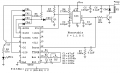
First pass at a schematic with *approximate* component values. C5 and C6 are power supply decoupling capacitors for the two IC's.

Note that because the initial voltage across C3 is 0 V, the 555 will be triggered at initial power-on, then again in 30 minutes and repeating. If an output pulse at power-on is not allowed, then add an R-C network to the 555 Reset pin to inhibit it until the charge on C3 has stabilized.

The 555 output pulse width is 11 seconds. You can change R2 and R4 to 1% or 0.1% tolerance for better accuracy, but the circuit is limited by the tolerance of the timing capacitors.

How accurate do the two timers have to be?

ak

!!4060-555-1-c.gif
 
Last edited:

AnalogKid

Joined Aug 1, 2013
12,115
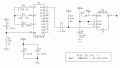
Here is a version without the 555,

Depending on the output current requirement, Q1 can be just about any small p-channel MOSFET.

R3-C3 set the output pulse width. Because a MOSFET has a relatively soft "knee" (the transition region between "on" and "off"), the output pulse width will vary from one component to the next and with room temperature. It also will vary with the value of Vcc. For example, the same circuit running on 5 V and on 12 V will have different output pulse widths.

And, the trailing edge of the output pulse will be somewhat sloped, because in this circuit Q1 turns on much faster than it turns off.

Delete C6 - oops.

ak

!!4060-555-2-c.gif
 
Last edited:

BobTPH

Joined Jun 5, 2013
11,503
How is that done since 10.5 seconds is not a binary factor of 1800 seconds?
Maybe my math was wrong, but I calculated 16384 counts for 1800 seconds, then 96 more for 10.5 seconds. Resetting when the 16384, 64, and 32 counts are high. This makes the 16374 out high for 10.5 seconds.
 

AnalogKid

Joined Aug 1, 2013
12,115
You are off by a factor of 2. It is 8192 counts for 1800 seconds.

Q14 starts out low, then goes high at count 8192, and goes low again (without an external Reset) at count 16384. You want the 4060 to be reset at count 8192 plus whatever equates to 10 seconds -ish. For your idea, each oscillator tick equals approx. 0.22 seconds at Q14, so 10 seconds equals 45.5 counts. The decoding is Q14, Q5, Q4, for 10.55 seconds.


ak
 
Last edited:

crutschow

Joined Mar 14, 2008
38,484
Maybe my math was wrong, but I calculated 16384 counts for 1800 seconds, then 96 more for 10.5 seconds. Resetting when the 16384, 64, and 32 counts are high. This makes the 16374 out high for 10.5 seconds.
Okay thanks. That makes sense.
I assume that would require a NAND gate with glitch protection.
 

BobTPH

Joined Jun 5, 2013
11,503
You are off by a factor of 2. It is 8192 counts for 1800 seconds.

Q14 starts out low, then goes high at count 8192, and goes low again (without an external Reset) at count 16384. You want the 4060 to be reset at count 8192 plus whatever equates to 10 seconds -ish. For your idea, each oscillator tick equals approx. 0.22 seconds at Q14, so 10 seconds equals 45.5 counts. The decoding is Q14, Q5, Q4, for 10.55 seconds.

ak
Thanks for correcting it. I had calculated 91 counts for 10 sec, off by a factor if two as you said. If the chip had a divide by two out, you get it to 10.26 seconds.
 

AnalogKid

Joined Aug 1, 2013
12,115
I assume that would require a NAND gate with glitch protection.
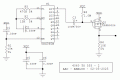
If a high-impedance output is OK, then this can be done with three diodes. No glitch protection necessary.

Because the 4060 is a ripple counter, the stage-to-stage delay works in your favor when decoding an upward count. Before 8192, Q14 is constantly low so there are no decoding glitches. When Q14 goes high at 8192, Q4 and Q5 already are low so no glitches there. Q5 is low when Q4 goes high, then Q4 is low before Q5 goes high, then Q5 stays high when Q4 finally goes high and completes the desired state.

ak
 
Last edited:

AnalogKid

Joined Aug 1, 2013
12,115
Another approach is to decrease the 4060 oscillator frequency such that the decoded output state is exactly 10 seconds. In this case, the delay between outputs is 28 minutes, 34 seconds. Of course there are many options for a compromise frequency where the delay is a little short and the output is a little long.

ak
 

crutschow

Joined Mar 14, 2008
38,484
Q14 starts out low, then goes high at count 8192, and goes low again (without an external Reset) at count 16384. You want the 4060 to be reset at count 8192 plus whatever equates to 10 seconds -ish. For your idea, each oscillator tick equals approx. 0.22 seconds at Q14, so 10 seconds equals 45.5 counts. The decoding is Q14, Q5, Q4, for 10.55 seconds.
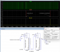
Below is the sim of that configuration:
I don't have a CD4061 model so I used two CD4040's in cascade to get 14 stages, with a 3-input AND gate to decode the three outputs.

So, for a 220ms period clock, Q14 goes high at about 1800 seconds and stays high for about 10.6 seconds as desired.

1738784975853.png
 
Last edited:
Top