50Hz Series RLC BSF

Thread Starter

henrylavery242

Joined Aug 8, 2024
74
Hello all,

I am trying to remove 50Hz signal from a circuit. The source comes from a LM741 op amp (which I believe to be 75 Ohms output impedance).It is an AC sine wave of approximately 7V.

I have been tasked to create an RLC Series band stop filter to remove this. I have chosen 300Ohms, 100micro farad and 100milli farad to remove the 50Hz signal.

Having build the circuit, I cannot get the voltage output of the filter increase as the frequency increases or decreases. Are there any reasons for this please?
 

Papabravo

Joined Feb 24, 2006
22,105
The TS wrote:
I have chosen 300Ohms, 100micro farad and 100milli farad
Those units describe a resistor and two capacitors, and that is not an RLC filter and would be unlikely to have a bandpass characteristic. As @atferrari has noted a complete schematic is essential to gathering the information required to help you. Even then I'm not sure you will be able to get the results you require. Your expectations for the performance of the filter are also relevant.
 

Thread Starter

henrylavery242

Joined Aug 8, 2024
74
The TS wrote:
I have chosen 300Ohms, 100micro farad and 100milli farad
Those units describe a resistor and two capacitors, and that is not an RLC filter and would be unlikely to have a bandpass characteristic. As @atferrari has noted a complete schematic is essential to gathering the information required to help you. Even then I'm not sure you will be able to get the results you require. Your expectations for the performance of the filter are also relevant.
Apologies I mean to put 100mH inductor
 

Thread Starter

henrylavery242

Joined Aug 8, 2024
74
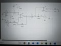
The op amps have a 12V plus or minus and are LM741. The issue I am having is that the difference amplifier creates 3V but regardless of the frequency I always get a approximately 100-300mV output of the input frequency
 

Papabravo

Joined Feb 24, 2006
22,105
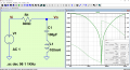
The filter is a notch filter (not a bandpass filter) with a center frequency of 50 Hz. and a bandwidth from -3dB to -3dB of approximately 480 Hz which is to be expected from a 2nd order filter section. It is not clear to me if this will do what you want it to do.
1723123292489.png
 

Papabravo

Joined Feb 24, 2006
22,105
Sorry I'm relatively new to electronics does this mean that it will work correctly?

Further to this, I am looking for a 100 microfarad capacitor which is non polarised. Could someone help?
A non-polarized capacitor of that value may be difficult to find. Passive components for low frequency applications are notoriously difficult to fabricate and/or purchase in reasonable sizes and affordable prices. On top of that most components are surface mount and the thru-hole equivalents are becoming increasingly difficult to obtain.
 

Thread Starter

henrylavery242

Joined Aug 8, 2024
74
A non-polarized capacitor of that value may be difficult to find. Passive components for low frequency applications are notoriously difficult to fabricate and/or purchase in reasonable sizes and affordable prices. On top of that most components are surface mount and the thru-hole equivalents are becoming increasingly difficult to obtain.

Would something like this work if I increase the voltage to somewhere between 6-8V AC?
 

Attachments

Thread Starter

henrylavery242

Joined Aug 8, 2024
74
Apologies, let me explain. My differential amplifier currently outputs 3V. If I increased this to between 6-8V, would I be able to use the capacitor I have I have shown in the link?
 

Papabravo

Joined Feb 24, 2006
22,105
You generally want the working voltage of a capacitor to be twice the maximum expected voltage. I think the 16V version would work. You mentioned AC in post #13, but you don't EVER want to subject an electrolytic capacitor to a reverse voltage. Thay can and will explode expelling HOT shrapnel - very dangerous.
 

Thread Starter

henrylavery242

Joined Aug 8, 2024
74
You generally want the working voltage of a capacitor to be twice the maximum expected voltage. I think the 16V version would work. You mentioned AC in post #13, but you don't EVER want to subject an electrolytic capacitor to a reverse voltage. Thay can and will explode expelling HOT shrapnel - very dangerous.
So this capacitor would not work for an alternating voltage? I essentially was to remove a 50hz sine wave which is approximately 6-8V. Would this be possible with this capacitor? Do you have any suggestions that I could use please?
 

Papabravo

Joined Feb 24, 2006
22,105
So this capacitor would not work for an alternating voltage? I essentially was to remove a 50hz sine wave which is approximately 6-8V. Would this be possible with this capacitor? Do you have any suggestions that I could use please?
No, it would not work for an AC voltage. To get the requires capacitance you might have to connect several devices in parallel.
 

Thread Starter

henrylavery242

Joined Aug 8, 2024
74
No, it would not work for an AC voltage. To get the requires capacitance you might have to connect several devices in parallel.
I had a look at the data sheet which I posted on #12, the capacitor says that it is bipolar but also electrolytic. Does this mean that it can be used ?
 
Top