I have ordered it and all the other parts... I will let you know how I get on. Thanks for the helpI'm not familiar with that terminology so somebody else will have to answer that. It sounds good, but I can't be certain.
Could you explain what the graph shows in more detail please?
Thanks, makes sense now. It was just the way it was laid out that threw me off. I will try and build the circuit in both configuration and let you know if I get it working.Two capacitors in series of 200uF is equivalent to 1 capacitor of 100uF. So, the effect of the filtering is unchanged. By connecting them in the opposing polarity they are not seeing any reverse voltage.
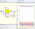
The green and purple graphs show the voltages X with respect to Y and GND with respect to Y and they are definitely positive as required by the electrolytic capacitors. In the lower set of graphs, the red trace is the input, the blue trace is the output of the opamp, and the green trace is the greatly attenuated output of the filter.
This will be an effective strategy for you.
What are the purposes of R1 R2 and R4?
Is this taking into account the difference amplifier before the RLC circuit?R1 and R2 determine the gain. R4 sets the correct, positive voltage on the oxide capacitors.
What type of capacitors do I need to be looking for for this system to work?Two capacitors in series of 200uF is equivalent to 1 capacitor of 100uF. So, the effect of the filtering is unchanged. By connecting them in the opposing polarity they are not seeing any reverse voltage.
The green and purple graphs show the voltages X with respect to Y and GND with respect to Y and they are definitely positive as required by the electrolytic capacitors. In the lower set of graphs, the red trace is the input, the blue trace is the output of the opamp, and the green trace is the greatly attenuated output of the filter.
This will be an effective strategy for you.
You can use electrolytic capacitors with a suitable working voltage. If the opamp has a ±12V supply then I would suggest capacitors with a working voltage of 25V, which is a standard value I believe. This gives 100% headroom if connected according to the schematic from @BordodynovWhat type of capacitors do I need to be looking for this system to work?
Henry
You can use electrolytic capacitors with a suitable working voltage. If the opamp has a ±12V supply then I would suggest capacitors with a working voltage of 25V, which is a standard value I believe. This gives 100% headroom if connected according to the schematic from @Bordodynov
You may have posted this reply before you finished the thought. Fortunately the forum allows you to edit you post to corrects such oopses.Hello mate, I built my circuit as per the schematic. I am inputting sine wave into the RLC circuit from the differential amplifier. However, my bandwidth

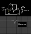
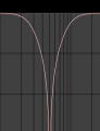
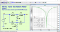
Hello, these all look tempting but I have been tasked to use the RLC BSF to complete the tasks. All I need to know is if have correctly set up my circuit. Basically have I done anything stupid and try and understand why it might not be working as expectedIf you are not happy with the bandwidth of the 2nd order RLC filter, perhaps the 3rd order Twin-Tee Notch will be more to your liking. The bandwidth of this 3td order filter is approximately 210 Hz as opposed to 480 Hz. for the 2nd order RLC filter. In low frequency work as has been pointed out by @tonyStewart inductors are seldom used for reasons that should be manifestly obvious.
View attachment 328932
0.3 mV is borderline undetectable. At DC your output should be 3 times your input is you used a gain of 3. That would correspond to the 0 dB line on the AC response plot. Work on that to start with.Hello mate, I built my circuit as per the schematic. I am inputting sine wave into the RLC circuit from the differential amplifier. However, my bandwidth is not performing as expected. Vout is approximately 0.3mV throughout all frequencies
0.3 mV is borderline undetectable. At DC your output should be 3 times your input is you used a gain of 3. That would correspond to the 0 dB line on the AC response plot. Work on that to start with.
ETA: You might want to share your working schematic or layout diagram with us just so we can double check your work.
Sorry, first things first then. Will my schematic work? I've run the simulator on multisim and it says it should.How come your schematic has no pin numbers on the inputs and outputs of the opamps, and how come your opamps have no explicit power connection and decoupling capacitors? How can you be sure you have wired it correctly.