50Hz Series RLC BSF

Papabravo

Joined Feb 24, 2006
22,105
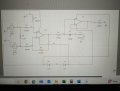
Sorry, first things first then. Will my schematic work? I've run the simulator on multisim and it says it should.

In terms of building how do I make the wires look neater
I don't know; there is not enough information.

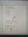
First you need to translate your functional schematic from the simulator in one that is annotated with reference designators for each component including the ICs. Each symbol that has wires going into and out needs pin numbers on those wires. Some people can construct a working circuit from that but others might need to make wire list of all the connections so they can check them off one at a time. Everybody has to find their comfort zone.
 

Thread Starter

henrylavery242

Joined Aug 8, 2024
74
I don't know; there is not enough information.

First you need to translate your functional schematic from the simulator in one that is annotated with reference designators for each component including the ICs. Each symbol that has wires going into and out needs pin numbers on those wires. Some people can construct a working circuit from that but others might need to make wire list of all the connections so they can check them off one at a time. Everybody has to find their comfort zone.
Okay, I'll work on it sorry. Do you have any suggests on better breadboard kits to use so that I can tidy up my wiring to make it look neater?
 

Papabravo

Joined Feb 24, 2006
22,105
You have numbers on the nets, but those won't help you wire things up. Each symbol needs to have the number of each pin on the physical package on the schematic so you see that U1.1 (Package U1 pin 1) goes to U3.4 (Package U3 pin 4). Does that convey the idea?
 

Thread Starter

henrylavery242

Joined Aug 8, 2024
74
You have numbers on the nets, but those won't help you wire things up. Each symbol needs to have the number of each pin on the physical package on the schematic so you see that U1.1 (Package U1 pin 1) goes to U3.4 (Package U3 pin 4). Does that convey the idea?
Kinds of yes, what software can I use to do this please?
 

Bordodynov

Joined May 20, 2015
3,431
Sorry, first things first then. Will my schematic work? I've run the simulator on multisim and it says it should.

In terms of building how do I make the wires look neater
I understand that you are a student and you are forced to use the program Multisim. This is a bad program, has many models with errors and often gives the wrong result. I created a topic on one of the forums in which I show this. But first, let your teachers explain the absurd result obtained in Mutisim:
mumu.png
 

Attachments

Thread Starter

henrylavery242

Joined Aug 8, 2024
74
I understand that you are a student and you are forced to use the program Multisim. This is a bad program, has many models with errors and often gives the wrong result. I created a topic on one of the forums in which I show this. But first, let your teachers explain the absurd result obtained in Mutisim:
View attachment 328958

I shall try download Kicad and post my schematic. Thanks massively for your help, I didn't realise how much more there is to building a circuit. I'm enjoying it though just very challenging
 

Thread Starter

henrylavery242

Joined Aug 8, 2024
74
Good afternoon,

I'm cur
Just print a copy of your schematic and annotate it by hand.

Kicad is a schematic capture and PCB layout package.
Hello, I'm currently redoing this. Could I have some help with how to calculate the CMRR of my circuit please if I am using LM741 op amps? And four 1k resistors with 5% tolerance
 

Thread Starter

henrylavery242

Joined Aug 8, 2024
74
The starting point is:
  1. Compute the common mode gain
  2. compute the differential gain
Do you know how to compute these values?
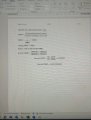
I have carried out calculations which I have found in literature Op amps by Clayton. Please see attached.

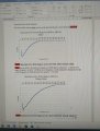
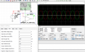
I have rebuilt the circuit and managed to get the circuit working with the electrolytic bipolar capacitor. The only thing I need to work out is: the attenuation at the center frequency is much less than in the Multisim simulation, although the band width is correct. What usually causes a reduction in attenuation? How could I possibly increase this?
 

Attachments

Thread Starter

henrylavery242

Joined Aug 8, 2024
74

Attachments

Papabravo

Joined Feb 24, 2006
22,105
In the context of CMRR, an input signal can be decomposed into two components. These components are a common mode component and a differential mode component. The Bode diagrams that you provided are not helpful in characterizing the input signal. You need to do this first so that you can compute or simulate the two different gains.
 

Thread Starter

henrylavery242

Joined Aug 8, 2024
74
In the context of CMRR, an input signal can be decomposed into two components. These components are a common mode component and a differential mode component. The Bode diagrams that you provided are not helpful in characterizing the input signal. You need to do this first so that you can compute or simulate the two different gains.
Hello again, are my calculations for CMRR incorrect then?

Further to this the input signal was fixed to 2V
 

Bordodynov

Joined May 20, 2015
3,431
I have carried out calculations which I have found in literature Op amps by Clayton. Please see attached.

I have rebuilt the circuit and managed to get the circuit working with the electrolytic bipolar capacitor. The only thing I need to work out is: the attenuation at the center frequency is much less than in the Multisim simulation, although the band width is correct. What usually causes a reduction in attenuation? How could I possibly increase this?
A common mistake of Multisim users is not taking into account the parasitic resistances of the inductance. When I gave my circuit, I used the series resistance of the inductance Rser. However, I used an underestimated value of this resistance, so as not to disappoint you in the filtering method. Measure the resistance of the inductance.
 

Thread Starter

henrylavery242

Joined Aug 8, 2024
74
A common mistake of Multisim users is not taking into account the parasitic resistances of the inductance. When I gave my circuit, I used the series resistance of the inductance Rser. However, I used an underestimated value of this resistance, so as not to disappoint you in the filtering method. Measure the resistance of the inductance.
This makes a lot of sense! The DC series resistance of inductor is 220ohms. Would there be any other limiting factors that would effect this please? I was to see if I can order different components to prove it that's all. I'm quite interest in understanding the circuit
 

tonyStewart

Joined May 8, 2012
238
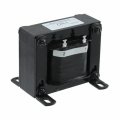
The reason you don't make practical RLC filters at low frequencies is the size and cost of the inductor to achieve the low DCR like `1.5 Ohm at 100 mH it will be expensive and bulky 1724017669873.jpeg
 
Top