50Hz Low Pass Filter

Thread Starter

Alkim Gokcen

Joined Mar 29, 2017
22
Hi All;
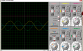
Im trying to filter a square wave to get a sin wave by using low pass filter.
I think it should be LC network filter,but i cant get the desired value although i made a proteus simulations which contains desired values.
But when i build the circuit,i cant get that sin wave.
Can you guys help me pls
Thanks you
 

MrAl

Joined Jun 17, 2014
11,474
so according to this LTSpice simulation, it should be workin? am i right? and may i get the reason of the difference between with-load and without-load?

Hello there,

First, i think you made a mistake in the calculation of the L and C values.
It looks like you tried to use w=1/sqrt(LC) which would only be right for a single stage passive LC filter.
A three stage passive filter has some interaction between stages, so for a three stage passive LC filter to tune to 50 Hz you would want to make the LC product equal to 2e-6 (that's 0.000002) and the units would be Farad Henries if you care to think of it that way.

So if you make the C value 20uf (for simplicity here) then the value of L would be:
L=0.000002/0.000020=0.1 Henries

Similarly, if you make the value of C 200uf then the value of L should be:
L=0.000002/0.000200=0.01 Henries

If i remember right if we decrease the inductor value (and hence increase the cap value to maintain LC=2e-6) then the response gets sharper, but it also then gets harder to adjust (if that matters). We could look at this in more detail though too.

So try changing the LC product to equal 2e-6 and see if you get better results.
This should handle load or no load, but there are some other considerations too such as the source input impedance which we dont know yet either.

With a cap value of 22uf that would mean L=0.090909 Henries.

BTW this filter functions more like a bandpass filter, which is good as long as it is tuned right.

ADDED LATER:
The short answer for the tuning is the product of L and C comes out to:
LC=1/(200*f^2)

where f is the frequency in Hertz, L is inductance in Henries, C is capacitance in Farads.
This approximation should be within 1 percent of exact.

The exact expression is a little more complicated:
LC=(5-sqrt(21)*sin(a)-sqrt(7)*cos(a))/(3*w^2)

where angle a is:
a=atan(sqrt(27))/3

We should however also have an expression for bandwidth.
 
Last edited:

Thread Starter

Alkim Gokcen

Joined Mar 29, 2017
22
Hello there,

First, i think you made a mistake in the calculation of the L and C values.
It looks like you tried to use w=1/sqrt(LC) which would only be right for a single stage passive LC filter.
A three stage passive filter has some interaction between stages, so for a three stage passive LC filter to tune to 50 Hz you would want to make the LC product equal to 2e-6 (that's 0.000002) and the units would be Farad Henries if you care to think of it that way.

So if you make the C value 20uf (for simplicity here) then the value of L would be:
L=0.000002/0.000020=0.1 Henries

Similarly, if you make the value of C 200uf then the value of L should be:
L=0.000002/0.000200=0.01 Henries

If i remember right if we decrease the inductor value (and hence increase the cap value to maintain LC=2e-6) then the response gets sharper, but it also then gets harder to adjust (if that matters). We could look at this in more detail though too.

So try changing the LC product to equal 2e-6 and see if you get better results.
This should handle load or no load, but there are some other considerations too such as the source input impedance which we dont know yet either.

With a cap value of 22uf that would mean L=0.090909 Henries.

BTW this filter functions more like a bandpass filter, which is good as long as it is tuned right.

ADDED LATER:
The short answer for the tuning is the product of L and C comes out to:
LC=1/(200*f^2)

where f is the frequency in Hertz, L is inductance in Henries, C is capacitance in Farads.
This approximation should be within 1 percent of exact.

The exact expression is a little more complicated:
LC=(5-sqrt(21)*sin(a)-sqrt(7)*cos(a))/(3*w^2)

where angle a is:
a=atan(sqrt(27))/3

We should however also have an expression for bandwidth.
Firt of all, thanks for your help,
I constracted the circuit in the lab,i could get a pure sinewave, butthe amplitude is 1/5 times smaller then the desired :(
 

MrAl

Joined Jun 17, 2014
11,474
Hi,

Ok well there are some unknowns yet so if you want to get a better idea on what the theory predicts you'll have to fill in the blanks.
We need to know the source impedance (or at least the resistance), the inductor ESR, and the load resistance.
We also have to know the exact value of the inductors and the exact value of the capacitors.
The exact values may be slightly different than the marked values, and with a very sharp response a small difference can make a big difference in the response amplitude.

Maybe we could look at the response with some resistance values that may be in effect in the real life circuit. You could do this in simulation also.
 
Top