5 volt Voltage regulator, using x2 14500 750mAh batteries.

Thread Starter

PriestSLC

Joined Apr 19, 2010
10
Hi guy's

After searching the net I came to find this site and thought that perhaps the help I am looking for may be here.

First off I will say I am handy enough with things to be either brilliant if I get it, or disastrous.

I want to build a voltage regulation circuit...

The power source will be 2 AW 14500 batteries in series, a 14500 produces 3.7 volts with a 750mAh rating.

I want to output to be 5 volts, or as close to it as possible.

The device that I am outputting to will have about a 2.5Ω to 4.5Ω resistance, I do not know if that matters.

Is there a simple radio shack way of doing this?

I also want to keep it as small as possible.

Thank you in advance for any pointers, directions you can help me with.
 

Thread Starter

PriestSLC

Joined Apr 19, 2010
10
I guess I should clarify, If I have instruction I can work with electronics, I can solder well, and given direction can put together most things, I was a radio shack, project with the springs kid, making all sorts of things with that kit, wires going all over from spring to spring.

Never went farther then that...

Now you are done laughing, I am not daft, I promise, If given direction I should be able to do it.

Thanks again.
 

eblc1388

Joined Nov 28, 2008
1,542
Ok.

The end of discharge of 3.7V cell is about 3.1V so with two in series you get about 6.2V. The load tells us that about 2A is required. A 7805 is not suitable as it requires more input voltage headroom and cannot meet the required output loading. A "Low drop out" LDO regulator is required.

The magic phase to search in Google is "5V LDO".

Here is an example of a component available from Digi-key: UCC283T-5, IC LINEAR REG LDO 5V 3A TO220-3.

Then get a datasheet from the part manufacturer website and it would have schematic on how to connect the part for 5V output.

## Important ##: If you go for the part above, make sure the one you get is the 3-pin type as the above part also available as a 5-pin type with adjustable output voltage.

Hope this helps.
 
Last edited:

Thread Starter

PriestSLC

Joined Apr 19, 2010
10
Ok.

The end of discharge of 3.7V cell is about 3.1V so with two in series you get about 6.2V. The load tells us that about 2A is required. A 7805 is not suitable as it requires more input voltage headroom and cannot meet the required output loading. A "Low drop out" LDO regulator is required.

The magic phase to search in Google is "5V LDO".

Here is an example of a component available from Digi-key: UCC283T-5, IC LINEAR REG LDO 5V 3A TO220-3.

Then get a datasheet from the part manufacturer website and it would have schematic on how to connect the part for 5V output.

## Important ##: If you go for the part above, make sure the one you get is the 3-pin type as the above part also available as a 5-pin type with adjustable output voltage.

Hope this helps.
Thank you eblc1388, that helps allot.
Is there any heat issues from this circuit that I am going to have to accomidate for? the internals for this project will more then likely be placed in a plastic project box.
 

eblc1388

Joined Nov 28, 2008
1,542
When the cells are freshly charged, they can have over 4.1V each and it makes the voltage input to the regulator at about 8.2V.

At a load current of 5V 2A, the heat dissipated by the regulator is 3.2x2=6.4W so the regulator will be very hot and require a heatsink.

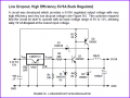
I don't know how long the load will be powered in your case but if it is for a long time until the batteries become discharged, then you might as well look also at switching regulator option.

But at 5V, 2A = 10W loading, assuming the regulator is 80% efficient, then you still have 2W to dissipate as heat. You get reduced energy lost at the expense of a more complex circuit arrangement.

An example from National semiconductor is as follow:

Source: http://www.national.com/appinfo/power/files/f5.pdf


Attachments

SgtWookie

Joined Jul 17, 2007
22,230
Using those batteries with that heavy of a load, you are not going to get much run time.

Maybe 12 to 15 minutes, if you're lucky. (That's not considering the losses in the regulation circuit.) The batteries will be very hot, and may even rupture.

The 750mAh rating is based on a 20-hour discharge rate, or 37.5mA.
 
Last edited:

Wendy

Joined Mar 24, 2008
23,803
Will 4.5V work?

Use 3 "D" cells.

If not use 4 recharables, most of them are 1.25V, which adds up to 5V. If you go for "C" or "D" cells they will have the current requirements. They can also be bought at Radio Shack, including the battery holders.
 

Thread Starter

PriestSLC

Joined Apr 19, 2010
10
Well size is a issue, the batteries and the regulation circuit need to be as small as possible. the unit will be providing 3 to 5 second power cycles, this is just to give a regulated burst of 5v. this is not going to be a always on device.
 

eblc1388

Joined Nov 28, 2008
1,542
A 3~5 seconds burst, then rest for how long before the next power burst?

This rest time will largely affects whether you would need to use a heatsink or not.
 

Thread Starter

PriestSLC

Joined Apr 19, 2010
10
it could be 3 to 5 burst's of 5 seconds with about 3 to 5 seconds between, and then about a 30 second to 90 second off line duration.
 

Thread Starter

PriestSLC

Joined Apr 19, 2010
10
For this one I want to control the amount of heat energy I am producing. I want to target about 15.5 watts of heat energy being produced by the coil.

I guess I could use a rectifier diode and kind of get the end result I am looking for, but it is also a education to me as well, yes a bit more complex, but fun at the same time.

Regardless of if it needs it or not, it's a mute point, I want to make it and see it work how I want it to :D
 

Thread Starter

PriestSLC

Joined Apr 19, 2010
10
Will 4.5V work?

Use 3 "D" cells.

If not use 4 recharables, most of them are 1.25V, which adds up to 5V. If you go for "C" or "D" cells they will have the current requirements. They can also be bought at Radio Shack, including the battery holders.
My goal is to try to use the power source I have selected, the batteries I will use are the AW 14500 double protected batteries.

If there is a failure, I should not have any explosions.

Size is a consideration for this project.
 

eblc1388

Joined Nov 28, 2008
1,542
it could be 3 to 5 burst's of 5 seconds with about 3 to 5 seconds between, and then about a 30 second to 90 second off line duration.
Such duty cycle would mean a heatsink be necessary inside a plastic box, unless you are using a switching mode power regulator then the heatsink size will be small or an area of copper on the printed circuit board will do the same job.
 

Thread Starter

PriestSLC

Joined Apr 19, 2010
10
Such duty cycle would mean a heatsink be necessary inside a plastic box, unless you are using a switching mode power regulator then the heatsink size will be small or an area of copper on the printed circuit board will do the same job.
I think I saw some heatsinks that would probably do the job online as well as at RS.

I think I am going to order all the part's x2 in case I mess it up, I will keep you updated on my progress, I plan to have it built within a month or so.

I appriciate your assistance with this, thank you for your time!
 

SgtWookie

Joined Jul 17, 2007
22,230
Is it your intention that the heater get to the point where it begins to glow red, or hotter?

If no, PWM may be enough to regulate the average current.
If yes, it's a bit more complex.
 
Top