 Facebook
 Google
 GitHub
 Linkedin
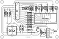
4-Digit UP/Down Counter Using Rotary Encoder


mikroC Source Code:
N.B: See attached for PCB artwork in Adobe Acrobat and hex file for PIC.
mikroC Source Code:
Code:
unsigned short i = 0;
unsigned short j = 0;
unsigned short scan = 0;
unsigned short rLeft = 0;
unsigned short rRight = 0;
unsigned short rotating = 0;
signed short ones = 0;
signed short tens = 0;
signed short hundreds = 0;
signed short thousands = 0;

#define dslpD PORTA.F1
#define dslpC PORTA.F0
#define dslpB PORTA.F3
#define dslpA PORTA.F2

#define segA PORTB.F7
#define segB PORTB.F5
#define segC PORTB.F3
#define segD PORTB.F2
#define segE PORTB.F1
#define segF PORTB.F6
#define segG PORTB.F4

#define rotary02 PORTB.F0
#define rotary01 PORTA.F4
#define rotary03 PORTB.F3

void num0()
{
  segA = 1;
  segB = 1;
  segC = 1;
  segD = 1;
  segE = 1;
  segF = 1;
}

void num1()
{
  segB = 1;
  segC = 1;
}

void num2()
{
  segA = 1;
  segB = 1;
  segG = 1;
  segD = 1;
  segE = 1;
}

void num3()
{
  segA = 1;
  segB = 1;
  segC = 1;
  segD = 1;
  segG = 1;
}

void num4()
{
  segF = 1;
  segG = 1;
  segB = 1;
  segC = 1;
}

void num5()
{
  segA = 1;
  segF = 1;
  segG = 1;
  segC = 1;
  segD = 1;
}

void num6()
{
  segA = 1;
  segC = 1;
  segD = 1;
  segE = 1;
  segF = 1;
  segG = 1;
}

void num7()
{
  segA = 1;
  segB = 1;
  segC = 1;
}

void num8()
{
  segA = 1;
  segB = 1;
  segC = 1;
  segD = 1;
  segE = 1;
  segF = 1;
  segG = 1;
}

void num9()
{
  segA = 1;
  segB = 1;
  segC = 1;
  segF = 1;
  segG = 1;
}

void blankDigit()
{
  segA = 0;
  segB = 0;
  segC = 0;
  segD = 0;
  segE = 0;
  segF = 0;
  segG = 0;
}

void displayOff()
{
   dslpA = 0;
   dslpB = 0;
   dslpC = 0;
   dslpD = 0;
}

void decCount()
{
   if (ones != 0 || tens != 0 || hundreds != 0 || thousands != 0)
   {
      ones--;

      if (ones < 0)
      {
         if (tens > 0)
         {
            ones = 9;
            tens --;
         }
         else if (hundreds > 0)
         {
            if (tens == 0)
            {
               tens = 9;
               ones = 9;
               hundreds --;
            }
         }
         else if (thousands > 0)
         {
            if (hundreds == 0)
            {
               if (tens == 0)
               {
                  tens = 9;
                  ones = 9;
                  hundreds = 9;
                  thousands --;
               }
            }
         }
      }
   }
}

void incCount()
{
   if (ones != 9 || tens != 9 || hundreds != 9 || thousands != 9)
   {
      ones++;

      if (ones > 9)
      {
         ones = 0;
         tens ++;
      }
      if (tens > 9)
      {
         tens = 0;
         hundreds ++;
      }
      if (hundreds > 9)
      {
         hundreds = 0;
         thousands ++;
      }
   }
}

void rstCount()
{
   ones = 0;
   tens = 0;
   hundreds = 0;
   thousands = 0;
}

void pollRotaryEncoder()
{
   TRISB = 0x09;

   if (rotary03 == 0)
   {
      rstCount();
   }

   TRISB = 0x01;

   if (rotary01 == 0)
   {
      if (rotary02 == 0)
      {
         rotating = 1;
      }
   }

   if (rotating == 1)
   {
      if (rotary01 == 1)
      {
         rRight = 1;
         rotating = 0;
      }
      if (rotary02 == 1)
      {
         rLeft = 1;
         rotating = 0;
      }
   }

   if (rotary01 == 1)
   {
      if (rotary02 == 1)
      {
         if (rleft == 1)
         {
            incCount();
            rLeft = 0;
         }

         if (rRight == 1)
         {
            decCount();
            rRight = 0;
         }
      }
   }
}

void setDigit(signed short digit)
{
   switch (digit)
   {
      case 0:
         num0();
         break;

      case 1:
         num1();
         break;

      case 2:
         num2();
         break;

      case 3:
         num3();
         break;

      case 4:
         num4();
         break;

      case 5:
         num5();
         break;

      case 6:
         num6();
         break;

      case 7:
         num7();
         break;

      case 8:
         num8();
         break;

      case 9:
         num9();
         break;

      case 10:
         blankDigit();
         break;

   }
}

void multiplexDisplays()
{
  displayOff();
  blankDigit();

   switch (scan)
   {
      case 0:
         setDigit(ones);
         dslpA = 1;
         break;

      case 1:
         setDigit(tens);
         dslpB = 1;
         break;

      case 2:
         setDigit(hundreds);
         dslpC = 1;
         break;

      case 3:
         setDigit(thousands);
         dslpD = 1;
         break;
   }

   scan++;

   if (scan == 4)
   {
      scan = 0;
   }
}

void main()
{
  CMCON = 7;
  TRISA = 0x10;
  TRISB = 0x01;
  PORTA = 0x00;
  PORTB = 0x00;

  while(1)
  {
     multiplexDisplays();
     Delay_us(100);
     pollRotaryEncoder();
  }
}[/SIZE]
N.B: See attached for PCB artwork in Adobe Acrobat and hex file for PIC.
Attachments
-
 231.9 KB Views: 2,170
 -
 218.4 KB Views: 693
 -
 189.7 KB Views: 1,868
 -
38.6 KB Views: 92
-
2.7 KB Views: 118
-
 210.4 KB Views: 1,545
Last edited by a moderator:
")


