4-20mA Current Loop receiver simulation

Thread Starter

chaitannya

Joined Apr 10, 2018
15
Hello Everyone,

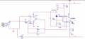
I am trying to design a 4-20mA current loop. I have referred Fig 19 from this IL300 datasheet. I wanted to test this circuit on pspice. Is there a way I can create a simple circuit for current loop transmitter to test it, something like a simple circuit driven by pot.

Regards,
Chaitannya
 

ericgibbs

Joined Jan 29, 2010
18,734
hi,
If I understand your query correctly, why don't you use a behavioural current source, set for PWL Ramp of 4mA to 20mA.?
E
EDIT:
This example is using LTSpice and the HCNR200 linear analog photo-coupler.
 

Attachments

Last edited:

dendad

Joined Feb 20, 2016
4,451
You can use an OpAmp as an ajustable current regulator to make a simple tester.
There is an example in the LM10 data sheet. The LM10 is an OpAmp and voltage ref in a package. Pretty handy.
http://www.ti.com/lit/ds/symlink/lm10.pdf

You may get lucky and be able to use an LM317 as an adjustable current source as the typical min current is 3.5mA.
But it could be higher, depending on device.

My tester is an LM385 I think.
If your load resistor is fixed, and so is your supply volts, just select a suitable resistor and series pot to keep it simple.
 
Last edited:

Thread Starter

chaitannya

Joined Apr 10, 2018
15
hi,
If I understand your query correctly, why don't you use a behavioural current source, set for PWL Ramp of 4mA to 20mA.?
E
EDIT:
This example is using LTSpice and the HCNR200 linear analog photo-coupler.
Just to simplify your circuit, R5 is the sense resistor ( the signal current is flowing through it), in the schematic, it is shown as a shunt resistor, but in the actual schematic, it should be in series of the current loop terminal ( neg supply line). Is my interpretation correct?

Regards,
Chaitannya
 

ericgibbs

Joined Jan 29, 2010
18,734
hi,
I used a Current source of 4 to 20mA through a 250R in order to provide a 1v thru 5v drive to the 1st OPA.
You could use the same current source to drive R1, OPA input resistor of the d/s typical circuit.

It could a simple circuit as described in post #3.

E
 

Thread Starter

chaitannya

Joined Apr 10, 2018
15
hi,
I used a Current source of 4 to 20mA through a 250R in order to provide a 1v thru 5v drive to the 1st OPA.
You could use the same current source to drive R1, OPA input resistor of the d/s typical circuit.

It could a simple circuit as described in post #3.

E
I think I have not understood well your reply. My doubt was regarding the resist R5 in shunt or series. I am referring to this diagram, which is a 2 wire current loop. The power source is at receiver circuit is powered entirely by the loop current, eliminating the need for an isolated power supply & the sense resistor is at position 3, which is in series.
 

Attachments

ericgibbs

Joined Jan 29, 2010
18,734
hi c.
The schematic is helpful but,
Could you post an image of your Pspice layout, so that I can better understand the problem.
E

EDIT:
In actual circuits I used this device, ref PDF.
 

Attachments

Last edited:

dendad

Joined Feb 20, 2016
4,451
There are a couple of things worth looking into for 4-20mA loop monitors..
First, do not select the termination resistor to give max ADC voltage at 20mA. Make the resistance a bit lower so you can actually read maybe 22mA.
Then you have a over current error sensing function. Otherwise, if the sensor is outputting over 20mA you will not know.
Also, and this is very important, make your reading end tolerant of full loop supply volts. In the real world, the sensor WILL be shorted or connected wrong in some way.
I add diode clamps and 50mA polyswitch PTC re-settable fuses. That saves blown ADCs and holes burnt through the PCBs as the termination resistor catches fire.
The sense resistor does not connect directly to the ADC input, but via an R/C filter. This also helps protect the ADC.

For instance, a simple tester could run from 12V.
Termination resistor = 220R.
Variable resistor = 3300R linear Pot.
Fixed series resistor = 330R. (sets max I)

This will give you a 3.12mA to 21.82mA test range.
ADC input volts = 0.69V to 4.80V range.
4-20tester.jpg
 
Last edited:

dendad

Joined Feb 20, 2016
4,451
Here is an example of the analog inputs for a board I did to sit on a BeagelBoneBlack.
There are 2 analog inputs, a motor current input and a 24V power monitor input.

AnalogIn.png
The resistor values are chosen to give a "4-20mA" in with the switch closed, and a "0-10V" input with it open.
This circuit configuration, although not perfect, has worked quite well in a number of products for years.
 
Top