3D Sense Shield2Go , TLV493d Calibration issue

Thread Starter

iamcalledusman

Joined Jun 1, 2019
15
Dear @Mark Hughes

Thanks for the nice effort that helped me a lot to interface the Sensor with Arduino .

I have attached the the source code , three image files.
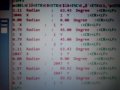
First image file is without the magnet
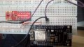
2nd image file I have place a magnet on the Sensor
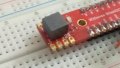
3rd image file I have flipped the magnet 180 degree and again placed on the sensor.

Issue is that if you see the first image without Magnet, Y=1 , and X= 2046 and after that , Y=1 , and X= 1 then Y=1 , and X= 2047

2nd image with Magnet, Y is varying from 0 to 4 and X from 1783 to 1785

3rd image same is the case with X and Y


Changes i have made :

I have made only disable Z and temperature into your code . And i am using Node MCU , D2 and D1 for the SDA and SCL pins .And one more changing is

const byte lpm[] = { B00000000, B00000001, B00000000, B10000000 }; // low power mode, 100ms , interrupt disable, temp disable


Thanks in Advance .

I need your expert opinion in this regard
 

Attachments

Mark Hughes

Joined Jun 14, 2016
409
Hi @iamcalledusman ,
Glad you're having fun with the TLV493D. So -- I've not yet played with a node MCU, but it looks like a neat little device. I get the impression that it is a 32-bit microcontroller -- can you confirm that? Also -- do you know its endianess? (big endian, little endian)
When I wrote the code -- I was making the device work on an 8-bit microcontroller. You are using a 32-bit microcontroller.
What that means is that my variables were maxed out at 0bxxxxxxxx long, and all of your variables are maxed out at 0bxxxxxxxxxxxxxxxxxxxxxxxxxxxxxxxx long. You don't need to mess around with all of the bit-masking that I did -- you can store the full register values in a single variable where I had to use an array. In short, my code allows the TLV493 to work on an underpowered microcontroller. It unnecessarily complicates things if you are allowed a 32-bit micro.

If I'm correct, it would explain why your values are changing significantly -- the bit-shifting and bitmasking likely no longer align to the correct values.
When I wrote the code, there was absolutely nothing available online -- I was the only game in town. But Infineon now has their own github for the device:
https://github.com/Infineon/TLV493D-A1B6-3DMagnetic-Sensor that has Arduino header libraries you can use. Additionally, it looks like some folks have already written code to get it going on a 32-bit micro:
https://github.com/Infineon/ESP8266-Sensor-Box/blob/master/examples/sensor_test/sensor_test.ino -- you'd just comment out the section for the other sensor.

Hope that helps. Let me know!
Mark
 

Thread Starter

iamcalledusman

Joined Jun 1, 2019
15
Dear @Mark Hughes

Thanks dear for the detailed answer . I appreciate a lot . My NodeMcu is liitle endian you are right .

To convert back into bigendian I used the following method

x = ( x >> 24 ) | (( x << 8) & 0x00ff0000 )| ((x >> 8) & 0x0000ff00) | ( x << 24) ;

but in return I got higher values like X= 456225 and Y= 456444 . So I commented the above line of code .


Your Next observation was about masking and shifting :
For this I did the following .Because I just want to print the Reg0 and 1 value directly. Without shifting and masking .

intdecodeX(inta, intb){
int ans = a ;

}
intdecodeYinta, intb){
int ans = a ;

}

but results were again X=0 to 3 and Y= 2047
and some times Y=0 to 3 and X= 2047 .

Thanks for the links they are very useful .But issue at my end is that I don't want to use the tlv493d libraries .Because my end target is to interface the CSR1010 with TLV493D. In that will use the I2C libraries as you did in this project .I don't want to use TLV493D libararies.
The purpose to interface TLV493D with nodemcu was that , I fully understand the behavior of the sensor and as well as addressing , read , write all these things .SO that when I move to CSR1010 it becomes easier for me to implement .

And the end again thanks for your efforts and support .I still need your expert opinion in this regard .

Thanks
 

Mark Hughes

Joined Jun 14, 2016
409
So I still haven't had a chance to jump into the datasheets for either device. But I think we can make some progress by simply cleaning up my original code. Using "int" is sloppy. I wasn't worried about it at the time because I only cared about using the code on the Arduino. The trouble is that "int" on the Arduino and "int" on your device might have different values. In short, my code is not portable.

Would you please replace all instances of "int" with "uint8_t" and let me know the results? Also -- do you mind uploading the latest copy of your code along with the latest copy of your results after the aforementioned changes?
Thanks!
Mark
 

Mark Hughes

Joined Jun 14, 2016
409
So -- let's go through and clean up the rest of the variables as well -- giving them fixed lengths.
Code:
#include <Wire.h>        // Wire header file for I2C and 2 wire
#include <math.h>

const uint8_t addr = 0x5E; // default address of magnetic sensor 0x5E or 0x3E
uint8_t rbuffer[10];       // store data from sensor read registers
uint8_t wbuffer[4];        // store data for sensor write registers.
uint8_t debugcounter;      // variable for debug counter
uint8_t delaytime = 50;     // time to wait before next read.  Delay will increase with errors.

//uint16_t  b0 ,b1 , b2 , b3;


// I2C pins

const uint8_t sdaPin = D2; // PIN_WIRE_SDA

const uint8_t sclPin = D1; // PIN_WIRE_SDL

/* 
*  Mode 1 is the second write register
*  Mode1_Int   Bxxxxx1xx  Interrupt Enable "1" / Disable "0"
*  Mode1_Fast  Bxxxxxx1x  Fast Mode Enable "1" / Disable "0" must be 0 for power down
*  Mode1_Low   Bxxxxxxx1  Low Power Mode Enable "1" / Disable "0"
* 
*  Mode 2 is the fourth write register
*  Mode2_T     B1xxxxxxx  Temperature Measurement Enable "1" / Disable "0"
*  Mode2_LP    Bx1xxxxxx  LP Period "1" = 12ms / "0"=100ms
*  Mode2_PT    Bxx1xxxxx  Parity test Enable "1" / Disable "0"
* 
*/

//     Example settings for Ultra-Low Power, Low Power, Fast Mode, and Power Down.
//                        Reg 1      Reg 2      Reg 3      Reg 4          
const uint8_t ulpm[] = { B00000000, B00000101, B00000000, B00000000 }; // ultra low power mode
//const uint8_t lpm[]  = { B00000000, B00000101, B00000000, B01000000 }; // low power mode,12ms
const uint8_t lpm[]  = { B00000000, B00000001, B00000000, B10000000 }; // low power mode, 100ms , interrupt disable, temp disable
const uint8_t fm[]   = { B00000000, B00000110, B00000000, B00000000 }; // fast mode (unsupported)
const uint8_t pd[]   = { B00000000, B00000001, B00000000, B00000000 }; // power down mode.


void setup() {
  Serial.begin(115200);      // Begin serial connection for debug.

  //Wire.begin();              // Begin I涎 wire communication

  Wire.begin(sdaPin, sclPin);


/* Read all registers, although only interested in configuration data
* stored in rbuffers 7,8,9, as 0-6 might be empty or invalid at the moment.
*/

  Wire.requestFrom(addr,sizeof(rbuffer));
  for(int i=0; i < sizeof(rbuffer); i++){
    rbuffer[i] = Wire.read();
    }
// Write Register 0H is non configurable.  Set all bits to 0
wbuffer[0] = B00000000;

// Read Register 7H 6:3 -> Write Register 1H 6:3
wbuffer[1] = rbuffer[7] & B01111000;

// Read Register 8H 7:0 -> Write Register 2H 7:0
wbuffer[2] = rbuffer[8];

// Read Register 9H 4:0 -> Write Register 3H 4:0 (Mod2)
wbuffer[3] = rbuffer[9] & B00001111;
 
// Set Power Mode (ulpm, lpm, fm, pd)
for(uint8_t i=0; i < sizeof(wbuffer); i++){
  wbuffer[i] |= lpm[i];
}

  Wire.beginTransmission(addr);       
  for(uint8_t i=0; i < sizeof(wbuffer); i++){
    Wire.write(wbuffer[i]);              
    }
  Wire.endTransmission();
}
//--- End of Setup --//

//--- Begin Main Program Loop --//
void loop() {
 
delay(delaytime); // wait time between reads.
// Read sensor registers and store in rbuffer
    Wire.requestFrom(addr,sizeof(rbuffer));
    for(uint8_t i=0; i < 6; i++){       // Should be 5
      rbuffer[i] = Wire.read();    //
    } 

// Goto decode functions below    
uint8_t x = decodeX(rbuffer[0],rbuffer[4]);
uint8_t y = decodeY(rbuffer[1],rbuffer[4]);

if(rbuffer[3] & B00000011 != 0){ // If bits are not 0, TLV is still reading Bx, By
  Serial.println("Data read error.............");
  //delaytime += 5;
}
//else if(rbuffer[5] & B01000000 != 0){ // T MUST BE 0 AT READ. IF 1 DATA IS TAMPERED
//  Serial.println("DATA IS TAMPERED.............");
//  delaytime += 5;
//}
//if(rbuffer[5] & B00010000 != 1){ // PD MUST BE 1 AT READ. IF 0 CONVERSION IS IN PROGRESS  ..... not verified
// Serial.println("CONVERSION IS IN PROGRESS.............");
  //delaytime += 10;
//}
else { Serial.print(x);         Serial.print("  X          :   "); Serial.print(y);                 Serial.print("  Y        :"); Serial.println();
     //  Serial.print(atan(y/x)); Serial.print("  Radian     :   "); Serial.print(atan(y/x)*57.2958); Serial.print("  Degree   :");Serial.println();
}

}

uint8_t decodeX(uint8_t a, uint8_t b){
/* Shift all bits of register 0 to the left 4 positions.  Bit 8 becomes bit 12.  Bits 0:3 shift in as zero.
* Determine which of bits 4:7 of register 4 are high, shift them to the right four places -- remask in case
* they shift in as something other than 0.  bitRead and bitWrite would be a bit more elegant in next version
* of code.
*/
uint8_t ans = ( a << 4 ) | (((b & B11110000) >> 4) & B00001111);
uint8_t ans=(0x0F)&b>>4;
  if( ans > 1023){ ans -= 2048; } // Interpret bit 12 as +/-
  return ans;
  }

uint8_t decodeY(uint8_t a, uint8_t b){
/* Shift all bits of register 1 to the left 4 positions.  Bit 8 becomes bit 12.  Bits 0-3 shift in as zero.
* Determine which of the first four bits of register 4 are true.  Add to previous answer.
*/

uint8_t ans = (a << 4) | (b & B00001111);
//uint8_t  ans=b;
  if( ans > 1024){ ans -= 2048;} // Interpret bit 12 as +/-
  return ans;
}
I'd really like to see some data coming out of those registers. -- if the typedef trick doesn't work, we'll need to go through the code and pepper in debug() statements to see where things are breaking down.
 

Thread Starter

iamcalledusman

Joined Jun 1, 2019
15
Dear sorry for delayed response , I just checked the code you have sent to me .
Once Again Thanks a lot for your time and efforts . I have attached the image docklight file . Same Output no change .

Thanks
BR
Muhammad Usman
 

Attachments

Mark Hughes

Joined Jun 14, 2016
409
Well then, the next step is I need to read the datasheet for your device and instead of "hacking" the old code, rewrite it for the 32-bit architecture.

I'll try to get to it this week.
 

Mark Hughes

Joined Jun 14, 2016
409
@ericgibbs @Raymond Genovese ,
Do either of you have experience with nodeMCU? I'd like to help this forum contributor port some of my old code -- but I'm afraid that I have too many questions about how nodeMCU works -- I can't find satisfactory documentation.
A couple of questions:
  • What is the endianness of the nodeMCU? I believe Arduino is little, and I get the impression that nodeMCU (ESP8266) can have big or little endian implementation. If there's a way to specify the endianness, it'll make life easier.
  • Is there anything I'm missing? It looks like the nodeMCU has some software that allows it to port Arduino sketches -- all of which are 8-bit, right? So the assembler is doing whatever tricks it needs to do to auto-port the code to the 32-bit architecture?
The way I see it, there are two things that can be happening -- first, the TLV493D isn't properly initialized. Second, the bit-masking is based on 8-bit architecture, the nodeMCU is 32.

Any advice would be appreciated -- or if there is someone else we can rope in to this, I'd appreciate it.

Thanks!
Mark
 

Thread Starter

iamcalledusman

Joined Jun 1, 2019
15
Dear again thanks for your help

Node MCU is little endian . I have written a good to test its endianness and it showed me little endian.

Question:
Is there anything I'm missing? It looks like the nodeMCU has some software that allows it to port Arduino sketches -- all of which are 8-bit, right? So the assembler is doing whatever tricks it needs to do to auto-port the code to the 32-bit architecture?

Ans:
I have to see it

The way I see it, there are two things that can be happening -- first, the TLV493D isn't properly initialized. Second, the bit-masking is based on 8-bit architecture, the nodeMCU is 32.

Yes you are right, I also think its not properly configured . I have attached two images
1)with magnet placed on TLV493D at static position
2)Without magnet .
if you see as the magnet is placed then fluctuations reduces and sensor goes to stability
But if no magnet then variation is more .

One question from you . When you implemented that code on Arduino them data was 100% stable ? No fluctuations at all ?

Thanks Again
 

Attachments

Mark Hughes

Joined Jun 14, 2016
409
Yes -- the readings should be stable out to the last bit of data.

Can you show me a picture of your implementation? Are you using the 3D2Go kit, or a homemade board with the TLV493D on it?
 

Mark Hughes

Joined Jun 14, 2016
409
So, one thing I would recommend is to dangle the sensor off the far edge of the board. It's rather sensitive and I wouldn't be surprised if the metal clips in that solderless breadboard aren't affecting your data in one way or another.

What about your magnet? How are you orienting the magnet in relation to the sensor? What is the field orientation of the magnet?
 

Thread Starter

iamcalledusman

Joined Jun 1, 2019
15
So, one thing I would recommend is to dangle the sensor off the far edge of the board. It's rather sensitive and I wouldn't be surprised if the metal clips in that solderless breadboard aren't affecting your data in one way or another.

What about your magnet? How are you orienting the magnet in relation to the sensor? What is the field orientation of the magnet?
What you recommend if I implement the hardware on vero board ? As for the magnet orientation is concerned I have place the magnet on the sensor . To get the changing values I flipped the magnet and again place on the sensor as shown in the picture .
 

Attachments

Thread Starter

iamcalledusman

Joined Jun 1, 2019
15
Hi, Now I have placed the sensor in air , no breadboard under it .But results are same . A very important observation which I want to share with you is that

I have added a serial print commands at the start up of code just to make sure that correct data is reading or not code is as mentioned below

Wire.requestFrom(addr,sizeof(rbuffer));
for(int i=0; i <sizeof(rbuffer); i++){
rbuffer =Wire.read();
}

// Lines added
for(int i=0; i <sizeof(rbuffer); i++){

Serial.print(rbuffer,HEX); Serial.print(" "); Serial.print(i+48); Serial.println();
}


Results are when no magnet:
when i reset the controller many times , each time new results came

on first time start up
Reg0 = 0x00
Reg1 = 0x00
Reg2 =0xFF

on 2nd time start up
Reg0 = 0x00
Reg1 = 0xFF
Reg2 =0xFF

on 3rd time start up
Reg0 = 0x00
Reg1 = 0x00
Reg2 =0x00

on 4th time start up
Reg0 = 0xFF
Reg1 = 0x00
Reg2 =0x00

data is changing randomly in first three registers but surprisingly

temp Registers Reg3 and Reg6 values remains almost same with very little variations. Not more then first 2 LSB change.

I am highly appreciated by your feedback regarding this issue .
 

Attachments

Thread Starter

iamcalledusman

Joined Jun 1, 2019
15
Hi , I have another observation . May b its helpful in solving the issue .

I have set the low power mode + temperature measure measurement disable

Mode2_T B1xxxxxxx Temperature Measurement Enable "1" / Disable "0"

const uint8_t lpm[] = { B00000000, B00000101, B00000000, B00000000 }; // low power mode, 100ms , interrupt disable, temp disable

after that I have printed the vaues of CH0 & CH1 on serial , it showed me the following output

FRM(3:2) & CH(1:0) & PD
00 00 1
10 00 1
11 00 0
01 00 0
11 00 1
01 00 1
10 00 0
00 00 0


PD bit has uniqueness 2 times 0 and 2 times 1 , conversion in process and completed ,

Although , I have set the following check as well

if(rbuffer[5] & B00010000 ==16){ // PD MUST BE 1 AT READ. IF 0 CONVERSION IS IN PROGRESS

// here I printed the CH , PD and FRM values
}
 

Thread Starter

iamcalledusman

Joined Jun 1, 2019
15
Hi , Sorry to disturb you again . I want to share few more observations:

These are values of first 5 registers when I have placed the static magnet (B0 -----> B5)
Change is only in B4 , because of first 4 LSB of X & Y
B0 B1 B2 B3 B4 B5
1 F7 B3 18 F3 39 <CR><LF>
1 F7 B3 10 81 3A <CR><LF>
1 F7 B3 14 C1 3C <CR><LF>
1 F7 B3 1C C1 39 <CR><LF>
1 F6 B3 10 CF 3A <CR><LF>
1 F7 B3 18 D2 3B <CR><LF>
1 F7 B3 1C D1 3A <CR><LF>
1 F7 B3 14 C2 3A <CR><LF>
1 F7 B3 18 B2 3B <CR><LF>
1 F7 B3 10 A7 39 <CR><LF>
1 F7 B3 14 D0 39 <CR><LF>
1 F7 B3 1C A2 39 <CR><LF>
1 F7 B3 14 B1 3B <CR><LF>
1 F7 B3 18 B2 39 <CR><LF>
1 F7 B3 10 B0 3B <CR><LF>
1 F7 B3 14 D1 39 <CR><LF>
1 F6 B3 1C CE 39 <CR><LF>
1 F7 B3 10 C2 39 <CR><LF>
1 F7 B3 18 D3 39 <CR><LF>
1 F7 B3 1C A2 39 <CR><LF>
1 F7 B3 14 C1 3A <CR><LF>

when No magnet then

Change is in B0 , B1 ,B2 and B4
B0 B1 B2 B3 B4 B5
0 FF 0 1C F 31 <CR><LF>
0 FF 0 14 1E 30 <CR><LF>
FF 0 FF 18 F0 3F <CR><LF>
0 0 0 10 1 30 <CR><LF>
FF 0 FF 14 F3 3E <CR><LF>
0 FF 0 1C F 30 <CR><LF>
0 0 0 10 31 30 <CR><LF>
FF 0 0 18 F0 30 <CR><LF>
FF 0 FF 1C F1 3F <CR><LF>
FF 0 0 14 E1 30 <CR><LF>
0 0 FF 18 11 3F <CR><LF>
0 0 FF 10 10 3E <CR><LF>
0 FF FF 14 3F 3F <CR><LF>
0 0 0 1C 11 30 <CR><LF>
0 0 FF 10 20 3F <CR><LF>
0 0 0 18 20 32 <CR><LF>
0 FF 0 1C 2F 32 <CR><LF>
0 0 FF 14 10 3F <CR><LF>

What you suggest is it right behavior or not ?
Thanks In Advance
 

Mark Hughes

Joined Jun 14, 2016
409
Hi @iamcalledusman ,
Sorry for not replying -- I'm traveling. I'll try to take a fresh look at things tomorrow.
Sorry!
Also -- have you tried the infineon forums? Has anyone experienced anything similar?

I'll get back to you soon,
Take care,
Mark
 
Top