350-Amp Voltage Regulator w/IGBTs @36V -> 15-28V variable

Thread Starter

newhavendave

Joined Mar 14, 2018
4
Hi, you have all been a huge help in my research over the last few days, brushing up on my circuits classes from college. I am a ME and am a bit outside of my AOE building a PSU for my welder concept (CV for GMAW).

*GOAL: I currently have a 36V (+3/-8) supply from SLA batts that I am trying to regulate (as selected) to anywhere from 15V (@60A max) to 28V @350A max).

I have taken the concept of a switching regulator to produce a final Pulsed DC output, with a waveform continuously- positive using a large Induction coil/choke. As new (cheaper/lighter) 'Inverter Welders' with this DC output seem to work fairly well.​

I have obtained an IGBT array consisting of of (3) 600V 200A two-transistor units [CM200DY-12H], mounted to a large heat sink, as the switching unit.​

Since the strike-arc produced is fairly large, I have a capacitor array on the 36V supply to minimize droop. I will also have an approx 400-600A circuit breaker for safety. On the output I have a 500A shunt to measure Current on prototype.​

*NOW, FOR YOUR HELP: I could use some assistance in designing the variable VR circuit for driving the IGBT gates with a feedback loop. I have seen IGBT gate drivers PCB units inexpensively from China (PWM input -> 0-10V). VR's are also sold cheap, but they have no provision to drive a MOSFET/IGBT using a separate Vsense (if you know any that exist let me know!)

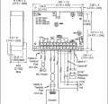
I have a NTE923D voltage regulator IC on hand that seems promising. But I don't know how to lay out the switching circuit, and if I need a remote current Inductor (prefer this since if I make more of these PSU's I don't want to use a shunt). Basically, I would like to have a simple PWM control the IGBT's, V-out selectable in 1.5V increments or infinitely-variable. Off-the shelf modules (China?) would be preferred.​

Thank you for your ideas!!​
 

Thread Starter

newhavendave

Joined Mar 14, 2018
4
ALSO: I have on hand many high-current components: SCR's, diodes (rectifiers), power resistors, large capacitors, induction coils and heat sinks (also a bunch of 0-90VDC motor drives, and 12V PSU's). I want this PSU design to be very-very reliable and rely on large high-current components vs. arrays of smaller ones.

I found this scientific paper (attachment) which seems promising on the efficiency aspect of high-power DC:DC conversion with IGBTs, 97% experimental resultant...
 

Attachments

Thread Starter

newhavendave

Joined Mar 14, 2018
4
UPDATE: OK scratch the IGBTs, I had them on hand, but they are slow and un-necessary for this low-voltage application.

I have found a PWM controller I would like to use with MOSFETs. Please advise if you think this will work, and if I can drive more than one MOSFET from the IC (as long as product of gate currents are within IC spec of 200ma) If it is a 1-1 pairing, I can use a synchronizable PWM and run them in parallel maybe?

Thanks!!

IRF4905 x6 75A MOSFETs P-channel 200watts ea
TPS40200 DC Buck PWM w/ 200mA P-channel gate drive
 

Attachments

shortbus

Joined Sep 30, 2009
10,045
*GOAL: I currently have a 36V (+3/-8) supply from SLA batts that I am trying to regulate (as selected) to anywhere from 15V (@60A max) to 28V @350A max).
While I hope you can make this work, I have my doubts. Battery powered Mig welders aren't to my knowledge available. And when you really look at the power used by a mains supplied Mig, you will quickly see why they aren't available, the size and cost of a battery bank and charger for that bank, makes even a gas powered welder a better way to go. I wish you well in your project, but if trying it myself, before spending money on electronic parts do some real world number crunching.
 

ebp

Joined Feb 8, 2018
2,332
I would expect this to be a difficult and time consuming undertaking and I have designed numerous industrial switch mode power supplies. Things that look OK on paper can be hideously difficult to get working because of all of the "parasitic" components in the circuit. Fast switching generates huge amounts of noise that can make control circuits unstable. Thermal management is in conflict with tight layout.

Let's start with some simple arithmetic. The FET you selected has nominally 20 milliohms of resistance, 6 in parallel 3.33 milliohms Your current is 350 A. The duty cycle of the switches is going to be in the range of 0.5 to 0.8. We'll use 0.75. The RMS currrent of a rectangular wave is equal to the peak x the square root of the duty cycle. 0.75 ^ 0.5 = 0.886, so the RMS current is about 303 A. Power in the FETs will be 303^2 x 0.0033 = 302 watts. That is a lot of heat to get rid of, and we are ignoring switching losses and the fact the waveforms aren't flat topped. 400 A peak is not unreasonable. You can probably keep the switching losses fairly low if you have a gate driver capable of a few amps peak and don't get carried away with switching frequency. 200 mA drive will get you melted FETs. The diode loss will be about 350 A x 0.7 V x .25 (RMS largely not applicable) - around 60 W for decent schottky diodes, rising to twice that for lower switch duty cycle. You are going to need a substantial blast of air over the heatsinks.

In practice no experienced designer would contemplate P channel FETs at this current. A single N channel device could easily cut the ON resistance to half of the 6 P channel devices. (Note I completely ignore the current rating and consider only the ON resistance.) Of course this means a high-side gate supply, but that is trivial in exchange for the dramatic reduction in losses.

A TO-220 package has leads smaller in cross section than an 18 AWG wire, which makes connection to conductors suitable for 350 A something of a problem. Even with very low resistance FETs you might want several just to make connection management tolerable. Don't ever believe you can dissipate 200 W in a single TO-220 package in any practical circumstances. Note the data sheet says popular up to 50 watts. I don't much like the TO-220 because it is hard to mount well for thermal management, though with several in parallel you could carefully screw them all to a copper bar and galvanically isolate the whole heatsink.

I could go on, but I won't.
 

shortbus

Joined Sep 30, 2009
10,045
A TO-220 package has leads smaller in cross section than an 18 AWG wire, which makes connection to conductors suitable for 350 A something of a problem.
That's why welders and other high amperage devices have gone to the SOT-227 package when using a mosfet. The mounting pad is also isolated from the internals of the package, which makes heat sinking much easier.

upload_2018-3-16_10-40-36.jpeg
 

ebp

Joined Feb 8, 2018
2,332
shortbus, I haven't looked at what you can get in that package for a long time. They've never been suitable for anything I've designed, so I haven't paid much attention. Given what is available these days you should be able to get some spectacular parts. It is a really good package for thermal management, provided you are willing to mill your heatsink face flat.

A lot of people underestimate how difficult the physical aspects like interconnect, galvanic isolation and thermal management can be in power circuitry, especially at high frequency.
 

shortbus

Joined Sep 30, 2009
10,045
Given what is available these days you should be able to get some spectacular parts
I just bought some for my electrical discharge machine project, again. I had some but the Rds was pretty high, since they were an older version. The new ones have a Rds of 0.06 ohm, little less than half of the old ones. They are a newer version but the newest ones are even better. The other route I could have taken was using ~6 TO-220 mosfets to do the same job and having to insulate the heat sinks. Way better using the SOT-227 package in my case.
 
Top