32-75V input to 12V,20A output Buck Converter using LM5116

Thread Starter

Junaid Arshad

Joined Jul 7, 2023
24
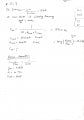
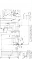
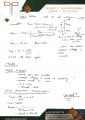
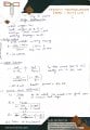
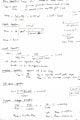
The buck converter is designed for 32-75V input and 12V,20A output, i designed it using the datasheet of LM5116, any consideration or suggestions from the experts in the design would be really appreciated.
 

Attachments

Thread Starter

Junaid Arshad

Joined Jul 7, 2023
24

Danko

Joined Nov 22, 2017
2,135
Thanks, so now i tried simulations on LTspice but the simulation is so slow it take alot of time,
but in TINA it shows following error, i have tried again and again reconnecting nodes all the wires but the same issue.
Please send ZIP with your .TSC file.
 

Danko

Joined Nov 22, 2017
2,135
The simulation is running now but it's very slow.
Each simulation for 50 ms was lasting 3 min,
10-core processor 4.5 GHz, Windows 11.
Result 1: your circuit as is.
Result 2: values of capacitors C12-C16 и C18 lowered to 1uF each.
Result 3: was added load 0.6 Ω on output.

1689931507589.png1689931550693.png1689931594220.png
 
Last edited:

Thread Starter

Junaid Arshad

Joined Jul 7, 2023
24
why the output of the design changes as load varies
Each simulation for 50 ms was lasting 3 min,
10-core processor 4.5 GHz, Windows 11.
Result 1: your circuit as is.
Result 2: values of capacitors C12-C16 и C18 lowered to 1uF each.
Result 3: was added load 0.6 Ω on output.

View attachment 298742View attachment 298743View attachment 298744
why the output voltage change when we vary the load could you please help me in the design, where the parameters need to be changed as we are also using feedback and comparators to adjust the voltage at 12V...........................:)
 

BobTPH

Joined Jun 5, 2013
11,463
Thanks, so now i tried simulations on LTspice but the simulation is so slow it take alot of time, but in TINA it shows following error, i have tried again and again reconnecting nodes all the wires but the same issue.
Look at the “ramp” pin on the chip. Follow the wire to the capacitor. Now follow the wire from the other side of the capacitor. It ends at another wire without connecting.
 
Hello @Junaid Arshad
Iam using LM5116 for creating buck converter
Help me out in designing UVLO
How to calculate Ruv1 and Ruv2 and what should be the expected voltage and current at UVLO pin
Design values
  1. Input Voltage-Vin=50V~60V
  2. Output Voltage-Vout=5.2V
  3. Output Current=10A
  4. Output Ripple voltage=100mV expected
  5. Efficiency-ɳ=95% expected
  6. Switching Frequency=250kHz fixed w.r.t to the application circuit in datasheet.

1. Can you explain How Ruv2 is calculated. As per above formula in 7.2.2.12 in datasheet i got
Ruv2>500 x Vin-max;
Ruv2>500 x 60;
Ruv2>30kohm
2. As 7.2.2.12 to calculate Ruvlo1 I need to Know Ruv2 value and VIN-min (UVLO desired shutdown voltage)
3. how exactly should I calculate Ruvlo2 and on what condition i should set VIN-min?
Thankyou
K Bindhu
 
Top