Facebook
 Google
 GitHub
 Linkedin
Hi,
Let me start by saying that my experience with circuits is somewhat limited, but I do have a basic understanding and have taught myself how to use the Eagle design software.
That being said...
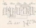
I am attempting to re-create a 30 year old circuit based on a schematic I was given. This circuit creates an oscillating pattern on a 10-segment LED array and then also is used to provide the logic for a much bigger, wall mounted halogen display.
Using a solderless breadboard, I was able to successfully re-create the circuit and it works perfectly. I then attempted to create the circuit in Eagle PCB and had some boards made. When I got them populated and powered it up, the LED array only cycled in one direction, not back and forth.
See this video for both the working breadboard and the malfunctioning PCB:
The circuit uses the following ICs:
4049 (Inverting Hex Buffer)
4510 (Up/Down Counter)
4028 (Decimal Decoder)
4013 (Flip Flop)
2804 (Driver Array)
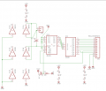
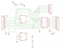
Attached also are screenshots of my Eagle layouts. This circuit needs to be split over 2 boards.
It's obviously a problem with my Eagle design. I am hoping that someone can spot the issue, because I have gone over it many times and can't find the problem. Or, perhaps someone could at least help me figure out which IC is causing this malfunction, so I can devote my energies just to that segment of the board.
For various reasons, I cannot post the original schematic here. If someone out there truly thinks they can help and needs the original schematic to troubleshoot, we might be able to share it privately.
I am sure there are easier and better ways to design a circuit to produce the desired outcome, but for this project, the circuit design must absolutely stay the same as I have described it.
Thank you!
Let me start by saying that my experience with circuits is somewhat limited, but I do have a basic understanding and have taught myself how to use the Eagle design software.
That being said...
I am attempting to re-create a 30 year old circuit based on a schematic I was given. This circuit creates an oscillating pattern on a 10-segment LED array and then also is used to provide the logic for a much bigger, wall mounted halogen display.
Using a solderless breadboard, I was able to successfully re-create the circuit and it works perfectly. I then attempted to create the circuit in Eagle PCB and had some boards made. When I got them populated and powered it up, the LED array only cycled in one direction, not back and forth.
See this video for both the working breadboard and the malfunctioning PCB:
The circuit uses the following ICs:
4049 (Inverting Hex Buffer)
4510 (Up/Down Counter)
4028 (Decimal Decoder)
4013 (Flip Flop)
2804 (Driver Array)
Attached also are screenshots of my Eagle layouts. This circuit needs to be split over 2 boards.
It's obviously a problem with my Eagle design. I am hoping that someone can spot the issue, because I have gone over it many times and can't find the problem. Or, perhaps someone could at least help me figure out which IC is causing this malfunction, so I can devote my energies just to that segment of the board.
For various reasons, I cannot post the original schematic here. If someone out there truly thinks they can help and needs the original schematic to troubleshoot, we might be able to share it privately.
I am sure there are easier and better ways to design a circuit to produce the desired outcome, but for this project, the circuit design must absolutely stay the same as I have described it.
Thank you!
Attachments
-
 18.1 KB Views: 42
 -
 19.2 KB Views: 40