3 Way Switch with 2 pins

Thread Starter

Stringbean781

Joined Oct 27, 2021
3
Hello,

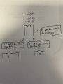
I am looking to make use of a tap shifter in my custom vehicle. The transmission module requires 2 different NO switches for the tap shift up and tap shift down. However, the 3 position shifter button in my car only has two pins. When I press +(the resistance between the two pins reads 630 Ohm) and when I press -(the resistance between the two pins reads 1995 Ohm). When I don't press + or -, the two pins are disconnected. I am attempting to have these resistance values open/close two different circuits. Basically, if I press +, it turns on a green light and If I press -, it turns on a red light. From the research I have done, it looks like a NPN And Gate would be useful. So if the resistance is between 500 and 750 Ohms, turn on the green light and if the resistance is between 1750 and 2000 Ohms, turn on the red light. Something like that. Thanks for any assistance!!
 

Ramussons

Joined May 3, 2013
1,404
Can you draw a schematic to show what you are looking for? It will save a whole lot of imagination.

The title points to a 2 Pole 3 Throw switch. The description is difficult to infer......
 

Thread Starter

Stringbean781

Joined Oct 27, 2021
3
I am unsure how the wiring is set up in the shifter. It's a 3 way switch with 2 pins, it's open when resting, reads 630 Ohms when pushed in one direction, and 1995 Ohms when pushed in the other. With these values, I would like to control two close 2 different switches that correspond to the two resistance values.
 

Attachments

panic mode

Joined Oct 10, 2011
2,715
Use 3-position toggle switch and add two resistors
1635433984151.png
and if you need two circuits to activate something else (LEDs etc.), use DPDT instead of SPDT.

otherwise... you would need to create a circuit that differentiate three states (open, 680, 1800) and has suitable outputs
 
Last edited:

Tonyr1084

Joined Sep 24, 2015
7,852
Use 3-position toggle switch and add two resistors
View attachment 251346
Three position (center off) "SPRING LOADED" switch is what sounds like what's being described. The illustration shows two lines exiting some sort of switch housing. I was about to make the same recommendation as panic mode

I found something similar with my wife's steering wheel radio control buttons. Different resistances mean different things to the radio. Volume up, down, mute/unmute, track up, down, mode (and so-on) all done with different resistance values. Likely some computer is seeing these resistances as part of a voltage divider circuit, which different voltages are interpreted to mean different commands. Likely the same thing with your paddle switches.
 

Thread Starter

Stringbean781

Joined Oct 27, 2021
3
You could use two comparators (e.g. LM339/393) to detect the resistance value and control two relays to give the switch closures.
This is exactly what I need! @panic mode drawing is exactly how the switch is wired in the shifter I believe. Also like @Tonyr1084 said, there must be some computer processing of the different voltages to do different commands. I already have this switch, but I am looking to turn it not into the different resistance values, but to use it as if it were two toggle switches. Along the lines of @crutschow reply. Can anyone help me with the wiring for this? Thank you for all these helpful responses!
 

Reloadron

Joined Jan 15, 2015
7,501
The lower section inside dotted lines is what you have as I see it.
Automotive Select.png
I would use as suggested a LM339 comparator and create two window comparators. Least I forget your switch has a center OFF so you have Momentary / OFF / Momentary selection about 630 Ohms or 1995 Ohms. I would place a 1 K Ohm resistor in series with your switch and take the Vout to your window comparators. Figure in an automotive application VCC will be between about 12 volts and maybe 14 volts give or take. Make your windows accordingly. Vout will give you a large enough difference to work with.

Another option is run Vout into a voltage divider and use a uC (micro controller) but unless you want to screw around with learning code and micro-controllers I would just, as suggested, use discreet components.

Ron
 

crutschow

Joined Mar 14, 2008
34,280
Below is the LTspice simulation of my take on a circuit for your requirements:
It uses a single-package, LM339 quad comparator plus some additional components for the comparison (one comparator in the package is not used.)

I grounded one of the switch terminals for operation, since I figured ground is likely easier to find on a vehicle then the battery voltage.

When the contact with the 630Ω resistance is closed (yellow trace) the D1 LED (green trace) and relay U1 are energized.

When the contact with the 1995Ω resistance is closed (blue trace) the D2 LED (red trace) and relay U4 are energized.

Of course, when no contact is closed, no relay is active.

U1b keeps the output of U1a low when U1c is active high to prevent both relays from being on at the same time (wired AND function).

1635530810675.png
 
Last edited:
Top