3-Phase Bridge Rectifier Simulation help needed

Thread Starter

mishra87

Joined Jan 17, 2016
1,037
Hey Experts,
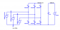
I am trying to simulate 3 phase rectifier in ltspice. I got this circuit from another AAC thread (https://forum.allaboutcircuits.com/threads/3-phase-rectifier-ltspice-simulation.19137/).
I am unable to figure out the problem in my circuit and why it is not working. I want to check the pulsating DC signal and Raw DC signal.
Can anyone figure out the problem in my circuit ?
.asc file is attached.
Thanks in Advance !
 

Attachments

ronsimpson

Joined Oct 7, 2019
3,037
Connect "Pulsating DC" to "RAW DC". Leaving RAW unconnected causes problems. I1 will pull C1 down to -infinity.

Knowing where to place ground can be a problem. Because you want to measure the voltage at C1 it is good to call that ground.
I tried your circuit, and it works now.
1670167135712.png

1670167444159.png
 

crutschow

Joined Mar 14, 2008
34,452
Here's a modified simulation that should show what you want:

For simulation purposes, I added D6 to isolate the Pulsating DC from the Raw DC, and added R1 to provide a discharge path for the voltage left on the diodes' small capacitance.
I switched the ground location to give proper output measurement voltages.

1670171618450.png
 
Last edited:

Thread Starter

mishra87

Joined Jan 17, 2016
1,037
Here's a modified simulation that should show what you want:

For simulation purposes, I added D6 to isolate the Pulsating DC from the Raw DC, and added R1 to provide a discharge path for the voltage left on the diodes' small capacitance.
I switched the ground location to give proper output measurement voltages.

View attachment 282133
Thank you very much.
1. in actual circuit do we really need D6 and R1 ?
2. Do you know why vpulsating is not 0v to vpeak ?
 

crutschow

Joined Mar 14, 2008
34,452
1. in actual circuit do we really need D6 and R1 ?
No.
No, as I noted, those were added only so you could see the difference between the Pulsating DC and the Raw DC in the simulation.
2. Do you know why vpulsating is not 0v to vpeak ?
How could it go to 0V with a 3-phase rectifier?
The pulsating voltage obviously can never go below the minimum instantaneous voltage magnitude of the 3-phases.
 
Last edited:
Top