2N3904 vs 2N3906 Rise and Fall times

ElectricSpidey

Joined Dec 2, 2017
3,347
If running @ 5 volts I would suspect that high side Darlington in the 555 is why it doesn't work connected directly to the 555.

Also using pin 3 to discharge the cap instead of pin 7 could have something to do with it.
 

Thread Starter

Tonyr1084

Joined Sep 24, 2015
9,744
If running @ 5 volts I would suspect that high side Darlington in the 555 is why it doesn't work connected directly to the 555.

Also using pin 3 to discharge the cap instead of pin 7 could have something to do with it.
Running 12 VDC.

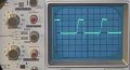
The wave form above is set to near zero. it should be practically zero but I think I'm using an Audio Taper pot instead of a Linear Taper. Let me check that.
 

Beau Schwabe

Joined Nov 7, 2019
186
With the schematic in post #16 make sure that the length to the IGBT gate is short because of antenna effects. Keep in mind that as the parasitic gate capacitance charges(NPN drive) or discharges (PNP drive) the associated transistor will conduct less and less down to a few pico amps. (Something hinted at in post #13 - Which BTW is exactly what happens)

On a simulator I connected an antenna to the gate of the IGBT through a 100nF cap and when the input to Q2 was LOW the shoot through current between Q1 and Q3 was about 200mA - this could cause either one to get warm. When Q2 was HIGH the shoot through current between Q1 and Q3 fell to about 70mA - Still excessive in my opinion.

Note: The output of the IGBT did not show any antenna noise and remained true to the input state on Q2 during the test. It was just Q1 and Q3 showing excessive current when an antenna was introduced to the IGBT gate.
 

Thread Starter

Tonyr1084

Joined Sep 24, 2015
9,744
Did you look at the signal with the scope probe connected to ground near the ground clip?
Just did. Looks even better. Only -2 VDC.

I'm getting the idea that my leads may be somewhat cheap. I've switched over to one I got from a school that teaches electronics to high school kids. They scrapped a bunch of equipment. Till now - my "go-to" probe has been the ones that came with my Hantek computer based scope. Touching and disconnecting the ground clip to the ground rail made an obvious and visible difference. So the ringing is not as bad as I thought it was.

I've got lots to learn yet. Thanks for the help. Now if I can figure out how to cool the 3906. Delaying its turn-on will probably help. But then that delays its turn-off too. I could end up with a hot 3904.

Totally open to suggestions at this point.
 

Chris65536

Joined Nov 11, 2019
270
Totally open to suggestions at this point.
From your scope pictures, it looks like you're running around 160KHz? That seems much higher than necessary for PWM. Maybe aim for around 1KHz to cut the switching losses. I don't really see that this would cause the 3906 to heat up though.

You could put a 100ohm resistor between the 3906 collector and ground, and monitor this on the scope to see if there's any short circuit current flowing through both BJTs. You could disconnect the IGBT for this test to eliminate the gate current spike.
 

crutschow

Joined Mar 14, 2008
38,627
Touching and disconnecting the ground clip to the ground rail made an obvious and visible difference.
You will get a lot of visible ringing and other artifacts if a short ground clip is not connected at a good ground point close to the point being measured.
For example, for best observation of high frequency switching signals, a probe short ground connection, such as shown below, is often used.

1579737430745.png
 

Thread Starter

Tonyr1084

Joined Sep 24, 2015
9,744
@Chris65536 Yes, the frequency is much higher than I initially wanted. I WAS using a 100K pot but it was flakey and worked sporadically. At first I thought my circuit had blown out. Turned out it was the pot. I grabbed what was available at the time - a 10K pot. It's an audio taper pot at that. So my PWM frequency doesn't remain constant. But I plan on getting new pots and tossing those cheap chinese throw-away pots in the throw-away bin. One of them measured 37K and it's marked 100K. So I have some work to do. Switching slower will also send less current through the transistors over time. If they're both on for 5 mS and I'm switching them at 100 Hz then that's half a second duration per minute that they're both on. A slower frequency means for the same duration they're on collectively a lot less time, and should not get as hot. They're not so hot they can't be touched, but the infrared thermometer is saying the 3906 is reaching 110˚ F. I'd rather it not be so hot. Not waste so much current. So a bigger pot, and maybe even a bigger capacitor (not electrolytic) will slow the frequency down. After all, this, in the end, is going to be running a DC fan motor.
 

shortbus

Joined Sep 30, 2009
10,049
18KHz to 20KHz is the common range of frequency in motor PWM circuits. To keep the magnetic/electrical noise under the hearing range.
 

Thread Starter

Tonyr1084

Joined Sep 24, 2015
9,744
18KHz to 20KHz is the common range of frequency in motor PWM circuits. To keep the magnetic/electrical noise under the hearing range.
Changing from a 10K pot to a 100K pot should put me just below your 18KHz number. As for noise in the hearing range - that's not a problem for me as I constantly hear frequencies near the 20KHz range all the time. Tinnitus. Sucks too. It's not likely I'll be hearing anything new in that range unless it's loud.

Please also remember that the pot I grabbed off the bench top is an audio taper. The frequency changes as well as the pulse duration. AND when I get to the end of the travel I don't approach zero ohms. I don't know why. Audio Taper pots are not well experienced in my hobby world.
 

Thread Starter

Tonyr1084

Joined Sep 24, 2015
9,744
I'm scheduled for a hearing test next week. But as I sit at night in the quiet - I listen to the different frequencies. Though at this time it's not known what frequencies they are - I can identify three major different high frequencies. I suppose I could build a frequency generator - a cheap one - and simulate a frequency, then scope it to see what that frequency is. But I'd estimate there are nearly seven different frequencies I hear. The price I pay for playing rock n roll drums for 8 years when I was young.

A few years back my wife bought for me a set of drums. Played them for about a year then decided my hearing was worth more than the drums. Used hearing protection (THIS TIME AROUND) but still, it seemed like my hearing was getting worse. So I sold them to a young man, probably about 16 years of age. I told him I was going to give him some advice. If he took my advice he would probably never thank me. But if he didn't take it he would wish he did. That advice was to protect his hearing. As I choked up while selling the drums - he could see I didn't want to give them up. But had to because of hearing losses and damaging noise - even with protection.
 

Thread Starter

Tonyr1084

Joined Sep 24, 2015
9,744
This is really challenging my last brain cell. The 2N3906 (see post #28) burned out. Attempted to use ONLY a 2N3904. That lasted about 5 minutes. Then burned out. Found an IRF630N laying around and looked up the specs on that. It's 19 amps. That should be able to handle the current. Don't know what's going on here - but that is running hot right now. After about 10 minutes of running a small fan the 630N is at 130˚F and appears to be rising. At the same time the IGBT, mounted on a heatsink is running at 102˚F. The PWM circuit is operating at 100% ON. I don't know why these devices are getting so hot. The 630N is not on a heatsink, but could be if need be. But the point is all the energy that is being converted to heat. This CAN'T be normal.

For those of you who are going to tell me the gate of the IGBT needs to be grounded - it's working without the ground.

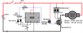
Here's my entire circuit:
1579886466634.png
 

Chris65536

Joined Nov 11, 2019
270
Put a shunt resistor in different locations and look for high currents. Connect your probe and ground across that resistor. A 1 ohm in series with the IGBT gate should show only tiny gate charging spikes on the scope. If there is any DC current there, maybe the IGBT is damaged?
 

Thread Starter

Tonyr1084

Joined Sep 24, 2015
9,744
Not sure I'm using the IR Thermometer. The further away, the cooler (obviously). The 630N is uncomfortable to touch. Why is it so warm? The 630 is rated Vgs Threshold is 2 to 4 volts and a max of ±20V. RDS ON is 0.2Ω.
 

Chris65536

Joined Nov 11, 2019
270
Not sure I'm using the IR Thermometer. The further away, the cooler (obviously). The 630N is uncomfortable to touch. Why is it so warm? The 630 is rated Vgs Threshold is 2 to 4 volts and a max of ±20V. RDS ON is 0.2Ω.
There must be some current going through the 630, which should not happen according to your schematic.
 

Thread Starter

Tonyr1084

Joined Sep 24, 2015
9,744
Put a shunt resistor in different locations and look for high currents. Connect your probe and ground across that resistor. A 1 ohm in series with the IGBT gate should show only tiny gate charging spikes on the scope. If there is any DC current there, maybe the IGBT is damaged?
Been wondering about that - the possibility of a damaged IGBT. From what I think I understand, the gate, once charged, should hold the IGBT ON until the gate gets grounded. But it has a beautiful square wave when turning on and off.
 
Top