2N3055's in parallel and heat

Thread Starter

John Potter

Joined Sep 24, 2016
51
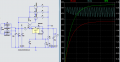
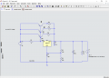
I have a 36V transformer that after rect. produces 3.3A at 52V. I wish to use a LM317AHVT (60V) with 2N3055 power transistors (60V).

If you run 2N3055's in parallel you are suppose d to have a resistor like a 0.1Ohm 10W from each emitter so that thermal runaway doesn't take place.Surely the resistor should be at least the output in watts ?

There are circuits on the Internet with this resistor on the base or collector but I think the emitter is correct ?

Could you possibly tell me how to calculate the value - Ohms and watts of this resistor. ? I understand this can be critical.

Honestly the Internet can be a nest of worms, there are many circuits that don't use a resistor at all.


On her page is a link to the circuit that states she removed the 0.1 Ohm 10W resistors as it limited her current output. This 20 odd Amp supply works fine.

Please advise.

I was considering using 4 x 2N3055's each at about 0.75A at 52V (39W each). I thought 3A from the transformer a safe limit. 1 heat sink per 2N3055 in an x pattern under a 125mm 0.5A fan blowing from outside the case down the heat sink fins with a 30mm gap at the bottom. The rear of the case is all vents. I may fit a 150mm 0.4A fan if the 125mm doesn't cover the heat sinks.

http://www.abl-heatsinks.co.uk/index.php?page=extrudedproduct&product=166

Mounting 2N3055's and heat dissipation.

There are 3 videos on this subject. Quite a down to earth approach but unfortunately nothing with metal to metal with heat compound - AND fan. Metal to metal with compound was by far the best. I can insulate the heat sinks. Extrapolating his results I should be able to draw 39W per 2N3055 at about 40C case temperature or less. The thermal resistance junction to case is 1.5 C/W. Max junction temp. is 200C. I should be running around 60 C


Any advice would be greatly appreciated.
 
Last edited:

ronv

Joined Nov 12, 2008
3,770
I have a 52V transformer that after rect. produces 3.3A at 52V. I wish to use either a LM317 or a LM338 with 2N3055 power transistors.

If you run 2N3055's in parallel you are suppose d to have a resistor like a 0.1Ohm 10W from each emitter so that thermal runaway doesn't take place.Surely the resistor should be at least the output in watts ?

There are circuits on the Internet with this resistor on the base or collector but I think the emitter is correct ?

Could you possibly tell me how to calculate the value - Ohms and watts of this resistor. ? I understand this can be critical.

Honestly the Internet can be a nest of worms, there are many circuits that don't use a resistor at all.


On her page is a link to the circuit that states she removed the 0.1 Ohm 10W resistors as it limited her current output. This 20 odd Amp supply works fine.

Please advise.

I was considering using 4 x 2N3055's each at about 0.75A at 52V (39W each). I thought 3A from the transformer a safe limit. 1 heat sink per 2N3055 in an x pattern under a 125mm 0.5A fan blowing from outside the case down the heat sink fins with a 30mm gap at the bottom. The rear of the case is all vents. I may fit a 150mm 0.4A fan if the 125mm doesn't cover the heat sinks.

http://www.abl-heatsinks.co.uk/index.php?page=extrudedproduct&product=166

Mounting 2N3055's and heat dissipation.

There are 3 videos on this subject. Quite a down to earth approach but unfortunately nothing with metal to metal with heat compound - AND fan. Metal to metal with compound was by far the best. I can insulate the heat sinks. Extrapolating his results I should be able to draw 39W per 2N3055 at about 40C case temperature or less. The thermal resistance junction to case is 1.5 C/W. Max junction temp. is 200C. I should be running around 60 C


Any advice would be greatly appreciated.
I didn't watch all the videos - but a few observations:
If the transformer is 52 volts ac the voltage after you add the filter capacitors will be around 72 volts as the caps store the peak voltage not the RMS voltage.
If you use a 317 for the basis of the supply you need to be careful of the maximum voltage rating.
The .1 ohm resistors are to compensate for variations it the transistors. You might get lucky without them, but it is a small price to pay to prevent a failure.
The power rating for your supply may not need to be so high. If you design it to retain the over current protection of the LM317 you can size them for that current or a fuse if you have one. But for the sake of discussion lets sat the maximum short circuit current is 6 amps (2 amps each 3055) The power would be I^2*R or 2.25 watts max. So maybe 5 watts.
You need to size the heat sink for the total power. So if you have 4 mounted on the same heatsink you will need a heatsink of about .25 C/watt.
Hope that helps.
 

Thread Starter

John Potter

Joined Sep 24, 2016
51
Thank you so much for your reply.

I meant that the transformer was 36V AC and 52V DC - sorry. The LM317AHVT will handle 60V. The LM338 won't - my mistake - again.
I have amended my post.

Could you possibly expand that formulae. I'm not sure what the ^ means. I take it the * is 'x'. I'm not used to keyboard mathematical symbols.

When you have the time the video's are well worth watching if your into power transistors. I was very surprised at the effect a fan has over passive.
It's over a factor of 3. That's the second link down. If one takes 6A then over 4 x 2N3055's that's 1.5A but I have thought of a thermal cut out and/or a fuse - say a 4A

What I don't understand it how much current does the emitter carry at a load of 0.75A at 52V passing through the 2N3305.
Have you any idea how these 0.1Ohm 5W resistors will effect the output.?

The reason I chose 4 separate heat sinks is that it's difficult to evenly cool 1 large one. The 2N3055 furthest from the fan must get hotter and that's the one that might go into thermal runaway. Even a fan from above would not produce an equal airflow. I thought 4 vertical heat sinks symmetrical with the fins edge on to the case fan would be at least equal.

Sounds like I might have heat sink problems. The best I can get in the case is about 0.6 C/W at a reasonable fan sound level. I could up the power but it's going to be rather noisy. The 1A fan has it's own 2A power supply. I may well have to reduce my total Amps.

May I ask how you calculated 0.25C/W ?

In one of the video's (No 2 - from 16 minutes) using a 2N3055 it's running at 56W without a fan at 80C and 49C with a fan. That was facing the fins. Through all the tests the heat sink lagged well behind the case temperature by about 20C even at the rear of the 2N3055.

I doubt very much if I'll exceed 100w in total.
I awfully sorry to be so thick but it's over 50 years since I dabbled in electronics
Thank you again for your help. I am on a rather steep learning curve.

Regards
.
 

ronv

Joined Nov 12, 2008
3,770
Thank you so much for your reply.

I meant that the transformer was 36V AC and 52V DC - sorry. The LM317AHVT will handle 60V. The LM338 won't - my mistake - again.
I have amended my post.
Good! That will help everything.:)
Could you possibly expand that formulae. I'm not sure what the ^ means. I take it the * is 'x'. I'm not used to keyboard mathematical symbols.
Sorry, I'm lazy sometimes.
The formula is for power I squared times R.

What I don't understand it how much current does the emitter carry at a load of 0.75A at 52V passing through the 2N3305.
Have you any idea how these 0.1Ohm 5W resistors will effect the output.?
It depends on the rest of your circuit. I like this one:

In this one there is little or no effect. There are others where it makes a small difference because the regulator can't adjust for the change in the voltage from a change in current. Let's say you set the voltage to 10 volts and your load is 3.3 ohms = 3 amps.
Each emitter will have .75 amps. So each resistor will drop only .075 volts. If you disconnect the load the voltage will rise .075 volts. Less than that with the one shown.


The reason I chose 4 separate heat sinks is that it's difficult to evenly cool 1 large one. The 2N3055 furthest from the fan must get hotter and that's the one that might go into thermal runaway. Even a fan from above would not produce an equal airflow. I thought 4 vertical heat sinks symmetrical with the fins edge on to the case fan would be at least equal.

Sounds like I might have heat sink problems. The best I can get in the case is about 0.6 C/W at a reasonable fan sound level. I could up the power but it's going to be rather noisy. The 1A fan has it's own 2A power supply. I may well have to reduce my total Amps.

May I ask how you calculated 0.25C/W ?
The worst is when you have the regulator set for low voltage and maximum current.
So 2 volts @ 3 amps means the transistors are dropping 50 volts at 3 amps or 150 watts. I was working with a single heatsink. So for your case ~38 watts each. Maybe 30C ambient so 30 C from heat. 0.8 C per watt is okay.

In one of the video's (No 2 - from 16 minutes) using a 2N3055 it's running at 56W without a fan at 80C and 49C with a fan. That was facing the fins. Through all the tests the heat sink lagged well behind the case temperature by about 20C even at the rear of the 2N3055.

I doubt very much if I'll exceed 100w in total.
I awfully sorry to be so thick but it's over 50 years since I dabbled in electronics
Thank you again for your help. I am on a rather steep learning curve.

Regards
.
I'll go watch it.
You doing just fine..:D
 

Thread Starter

John Potter

Joined Sep 24, 2016
51
Thanks ronv, I made a mess of that LM thing.
No, your not being lazy it's me being thick - trust me I know nothing.

It looks a fairly simple circuit, not much more than the basic one. Is that a 'choke' or whatever, sorry I don't know.
What's the 7812 doing is that for the Light program or the Home service - maybe fans? What's the second variable resistor for - a trimmer?
I'm not worried about 0.075V but while I'm on I might as well do the best I know how to - which isn't much.
Any chance you could fill in the value for that 'choke' or whatever.
Some of the circuits I have looked at make my brain urt. I think I could manage the one you have shown.

Some years ago a friend made me a small linear regulator for a 'Digital Dream' camera that ate batteries.
I had it in my trouser pocked when I first used it. No heat sink. I still have the scar.
That camera could flatten a set of good AA's in 3 flashes.

I do like the idea of a thermal cut out on each 2N3055 - to cut the power from all of them of course. They don't cost much. Pity Hotpoint dont use them in their tumble dryers, our old spare dryer has one. I thought 70C or thereabouts ? It's an awful lot of heat to dissipate.

I am building a 22V AC - 20V DC 4A + 2 x 1000uF 60V caps linear regulator first. I'm trying 3 x LM338's on a 100W PC processor heat sink with a fan and a case fan . I added a few turns to an old 12V battery charger. Even that's going to be 80W but I can use that for lower volts. Everything is made from old PC power supply cases. I should add these emitter resistors to the LM338's ?

The main 51V is 2 joined together. It's a bit tight for the heat sinks but I can always add another one.
The photo was when I had the transformer a 18V AC hence the small size caps.

20V power supply.jpg

I have added a couple of photo's of the 7A battery charger I have just finished. there are 2 x 50W halogen bulbs in series with the output so that it's impossible to short it out. Awesome at night. Separate windings for the fan. Makes a good room heater.
Charger 1.jpg 4Amp.jpg Power.jpg

Thanks for you help. I have learned more from you than weeks on the Internet. I was getting a bit disheartened.
 

ScottWang

Joined Aug 23, 2012
7,409
Vdc out = 36Vac * 1.414 = 50.9Vdc, why is 52V?
Safety voltage = 50.9Vdc - 3V = 47.9Vdc, it means that it could be use the Vmax less 47.9V.

When the load add in then the output voltage will be drop a little, it depends on the resistance of load, so if you want to get a safety voltage for 52V then it should be calculates like this:
Vac in = (52Vdc + 3Vdc) *0.707 = 38.88Vac

The resistor put in series with the emitter as 0.1Ω or 0.2Ω, that is to protect the Vbe of bjt when you in parallel with two 2N3055, those resistors were used to avoid the Vbe has different voltage drop when Ib flows through B,E, if you added the resistors then the different voltage drop will be cross on the resistors, so the Vbe of bjt will be have the their own voltage drop.

How much watts of the Re(0.1Ω or 0.2Ω), it depends on how much current flows through the Ie,
Watts = Ie * Re, choose 3~5 times of calculation watts.

A 2N3055 has 15A Imax rating, only provides 0.7A is too less, it can be drive more as 1.5~2A, but don't drive it too high, if you have more space of case then using 0.7A can be reducing the power dissipation of 2N3055.
 

Thread Starter

John Potter

Joined Sep 24, 2016
51
Hello ScottWang - thanks for the reply.
The transformer is rated at 36V output at 230V. This is to conform with EEC regulations regardless of the fact that the UK is 240V. Mine is 245V. Therefore the output is not 36V but 38.35V, There is also a tolerance on the windings. The actual V after rect. cap. and a small load was close to 52V.
The offload V at the 230V rating is stated as 19.6V
http://www.farnell.com/datasheets/1829278.pdf
MCTA160/18

I mentioned a 36V power supply and was given this 36V AC toroidal transformer as a present. I'm quite happy to loose a few volts. I do have some 0.1Ohm x 5W resistors and I was going to fit them and use an infra red thermometer to check the 2N3055 case temperatures under load. I can always add them in series until I find the best value.

I have read that the emitter resister may have to go beyond 0.2Ohm if the 2N3055's are wildly different. I have seen circuits where it is 0.47Ohm. I bought mine from a reputable stockist all together. I would prefer to be on the safe side as V is higher than I was aiming at anyway.

I believe I have just over 3A at 52V therefore I wanted to cover or get as close as is practicable to the max current which is 0.75A / 2N3055. I doubt I will ever use this amount but better to be safe. At 52V that almost 40W / 2N3055.

Thanks again for you advice.
 

ScottWang

Joined Aug 23, 2012
7,409
If the Re is 0.1Ω then the watts will be as:
V_Re = Ie * Re
= 0.75A * 0.1Ω
= 0.075V

W_Re = V_Re * Ie
= 0.075V * 0.75A
= 0.056 Watts

Choose W_Re = 0.056 W * 5 = 0.28 Watts
So if you choosing 1 watts for Re is enough.
-------------------------------------------------------
If the Re is 0.2Ω then the watts will be as:
V_Re = Ie * Re
= 0.75A * 0.2Ω
= 0.15V

W_Re = V_Re * Ie
= 0.15V * 0.75A
= 0.1125 Watts

Choose W_Re = 0.1125 W * 5 = 0.5625 Watts
So if you choosing 1 watts for Re is enough, if you want to choose 2W is also ok, but if you using 5W is a little high.

And how much current(Iac) from transformer?
 

Thread Starter

John Potter

Joined Sep 24, 2016
51
Thanks ScotWang
I'll fit a 2W - to be sure to be sure. Only because I have some.
If the imbalance between the 2N3055's is on the high side 0.1Ohms may need to go up I understand.
How would I check for any imbalance with a meter ? I have an old auto ranging Fluke.
I also have an infra red thermometer. It's fine at 100C so I expect it would see any major heat difference between the 4 x 2N3055's cases.

It's rated at 4.44A at 36VAC
I assume that the overall Watts from the transformer more or less stays the same (- the bridge rect.) from AC to DC and that works out at 3.27A.
I thought I would work on a Max of 3A. Normal running will be much less than that.
Because of this 230V rating and my 245V mains - the data sheet says 160VA but I assume the extra voltage takes it up to 170VA. How that effects the Amps I have no idea.

Thanks again.
 

ScottWang

Joined Aug 23, 2012
7,409
How would I check for any imbalance with a meter ? I have an old auto ranging Fluke.
What imbalance, V_Re or I_Re? (Re is the resistor in series with Ve as 0.1Ω.)
You can get I_Re from measuring V_Re and I_Re = V_Re/Re
You can get all of I_Re1~I_Re4 from measuring V_Re1~V_Re4

I also have an infra red thermometer. It's fine at 100C so I expect it would see any major heat difference between the 4 x 2N3055's cases.
When you testing the Vmax with Imax to get the Wmax output, the best temperature is around 60°C or less and should be continuing at least 1 hour and the temperature no increasing, if the temperature is too high then you have to active the fan to reducing the heat., if the circuit there is no temperature detector then the fan should be active with the power up.

It's rated at 4.44A at 36VAC
I assume that the overall Watts from the transformer more or less stays the same (- the bridge rect.) from AC to DC and that works out at 3.27A.
I thought I would work on a Max of 3A. Normal running will be much less than that.
If the real voltage is 38.35Vac then I will assuming that the ac current like as:
V_err = 38.35V - 36V = 2.35V
P_err % = 2.35V/38.35V = 0.0612 = 6.12%
Iout ac = 4.44A (1+0.0612) = 4.71 Aac
Iout dc = 4.71 Iac / 1.414
= 3.33 Idc

Vout dc = 38.35Vac *1.414
= 54.227 Vdc
Vout_LM317 = 54.227 Vdc - 3V = 51.227V
So the max voltage output from LM317 is 51.227V without load
 

ronv

Joined Nov 12, 2008
3,770
Thanks ronv, I made a mess of that LM thing.
No, your not being lazy it's me being thick - trust me I know nothing.

It looks a fairly simple circuit, not much more than the basic one. Is that a 'choke' or whatever, sorry I don't know.
What's the 7812 doing is that for the Light program or the Home service - maybe fans? What's the second variable resistor for - a trimmer?
I'm not worried about 0.075V but while I'm on I might as well do the best I know how to - which isn't much.
Any chance you could fill in the value for that 'choke' or whatever.
Some of the circuits I have looked at make my brain urt. I think I could manage the one you have shown.

Some years ago a friend made me a small linear regulator for a 'Digital Dream' camera that ate batteries.
I had it in my trouser pocked when I first used it. No heat sink. I still have the scar.
That camera could flatten a set of good AA's in 3 flashes.

I do like the idea of a thermal cut out on each 2N3055 - to cut the power from all of them of course. They don't cost much. Pity Hotpoint dont use them in their tumble dryers, our old spare dryer has one. I thought 70C or thereabouts ? It's an awful lot of heat to dissipate.

I am building a 22V AC - 20V DC 4A + 2 x 1000uF 60V caps linear regulator first. I'm trying 3 x LM338's on a 100W PC processor heat sink with a fan and a case fan . I added a few turns to an old 12V battery charger. Even that's going to be 80W but I can use that for lower volts. Everything is made from old PC power supply cases. I should add these emitter resistors to the LM338's ?

The main 51V is 2 joined together. It's a bit tight for the heat sinks but I can always add another one.
The photo was when I had the transformer a 18V AC hence the small size caps.

View attachment 115693

I have added a couple of photo's of the 7A battery charger I have just finished. there are 2 x 50W halogen bulbs in series with the output so that it's impossible to short it out. Awesome at night. Separate windings for the fan. Makes a good room heater.
View attachment 115689 View attachment 115690 View attachment 115691

Thanks for you help. I have learned more from you than weeks on the Internet. I was getting a bit disheartened.
Cool.
Yes, there is some unneeded stuff in the diagram.
Here is a simulation of the whole thing.
Yes, the extra pot is a fine adjust for the voltage.
 

Attachments

Thread Starter

John Potter

Joined Sep 24, 2016
51
By ek ScottWang your on form tonight - thanks. My Internet connection went fut but Virgin Media sorted it out in 40 Mins. The phoo phoo valve was bent.

I am sorry but your equations are rather difficult for me to follow as I am not certain of some of them.
V_Re, I_Re, I_Re1~1_Re4, etc, etc.
I am a complete novice. Pretend I am 9 years old and no nuffinc.

I agree though that my Amps out is close enough to yours and so is the Volts. Due to the tolerances in the windings of the transformer ( I guess) did give me a reading of 51.8V odd. Hence 52V. It's nice to know I am not far enough out that could make any difference.

In regards to 'the imbalance' I read that the emitter resistor may need to be increased if there was still a transistor taking more volts than it should. It was suggested 0.47Ohms. I have even seen this value on several circuits along with 0.22Ohms. I thought it was someone being extra cautious.

Do remember I got this off the Internet - hence my statement at the beginning of this thread 'Honestly the Internet can be a nest of worms'. I am trying to sort out the wheat from the chaff through kind people like yourself.

Sorry about my lack of knowledge about electronic maths but it's totally new to me. I was a mechanical engineer.

Thanks so much for your help. I just hope my Internet connection holds out. They fitted a new modem on Saturday - didn't last long before trouble. It's usually very good.
 

ScottWang

Joined Aug 23, 2012
7,409
V_Re, I_Re, I_Re1~1_Re4, etc, etc.
Sorry.
V : Voltage, I : Current
The transistor of 2N3055 has C(Collector), B(Base), E(Emitter), three pins.
Re : the Resistor in series with emitter of 2N3055
Ve : The Voltage of emitter of 2N3055
V_Re : the voltage cross on Re
I_Re : the current flows through Re
Vbe : The Voltage cross on b(base), e(emitter) of 2N3055

You have four 2N3055, so they could be labeling like these --
The four Re resistor like as Re1, Re2, Re3, Re4.
Ve1 : the voltage of emitter of 2N3055-1, sometimes it also means e(emitter) pin
Ve2 : the voltage of emitter of 2N3055-2, sometimes it also means e(emitter) pin
Ve3 : the voltage of emitter of 2N3055-3, sometimes it also means e(emitter) pin
Ve4 : the voltage of emitter of 2N3055-4, sometimes it also means e(emitter) pin

V_Re1 : the voltage cross on Re1(the resistor in series with 2N3055-1)
V_Re2 : the voltage cross on Re2(the resistor in series with 2N3055-2)
V_Re3 : the voltage cross on Re3(the resistor in series with 2N3055-3)
V_Re3 : the voltage cross on Re4(the resistor in series with 2N3055-4)

I_Re1 : the current flows through Re1(the resistor in series with 2N3055-1)
I_Re2 : the current flows through Re2(the resistor in series with 2N3055-2)
I_Re3 : the current flows through Re3(the resistor in series with 2N3055-3)
I_Re4 : the current flows through Re4(the resistor in series with 2N3055-4)

So you can measure the Vbe1, Vbe2, Vbe3, Vbe4 and V_Re1, V_Re2, V_Re3, V_Re4.

If you can't make sure how precisely of the values of Re(0.1x Ω or 0.2x Ω) then if you want to get the I_Re through measure the V_Re as I_Re = V_Re/Re, it may has the precision issue, so you have to connects the current meter in series with Re1~Re4 to measure their current one by one.
 

Thread Starter

John Potter

Joined Sep 24, 2016
51
ThanksScotWang - perfect. I'll copy paste that into my notes.

Whilst in the loo contemplating the meaning of life this morning I had a revelation. It didn't hurt much.

I have seen 'centre tap' circuits and had a quick look but I'm afraid it was a case of 'duh'.
The transformer I have is 18VAC x 4.44A + 18VAC x 4.44A therefore I think centre tapped ?
I had it wired for 18VAC at 8.88A. I did check I could with CPC Farnell first. I then decided on 36VAC at 4.44A.

Working on the theory 'you can only ask'.
Is it possible to switch between 26V DC x 3.3A and 52 DC x 3.3A. I don't think I see a problem with the switching arrangement at the output from the transformer. Would everything that follows on work ?
If you halve the difference in Volts between Input and load then you would halve the Watts on the 2N3055's - and heat ?
It would be nice if I was right otherwise I shall have to go back on my medication.
 

ScottWang

Joined Aug 23, 2012
7,409
The transformer that I can find are 18V-0V or 18V-0V-18V, I can't see the centre tapped from the pictures that you uploaded, if the transformer has the centre tapped as 18V-0V-18V, probably you can make a dual power supply as the second circuit below, and you can using the power as 0~+26V, there are two methods to get 0~+26V.
1. 0V, +26V two terminals.
2. 0V, -26V two terminals (if you using this way then the 0V will be like as the normal +26V and the -26V will be like as 0V).

And also you can get 0~52V(+26V, -26V, only using two terminals, if you using this way then the +26V will be like as the normal +52V and the -26V will be like as 0V).


If you halve the difference in Volts between Input and load then you would halve the Watts on the 2N3055's - and heat ?
Concern about the power dissipation become useless, so some ee players will buy the transformer as 18V-12V-0V-12V-18V, so when they just need to using the lower voltage then they can switching to 12V-0V-12V and switching to 18V-0V-18V when they need to using the higher voltage.
 

Kermit2

Joined Feb 5, 2010
4,162
You can cut the current in half and you can cut the voltage in half but the heat (watts) is different.
Current (squared) times resistance equals watts.
So going from 4 amps to 2 amps halves the current, but a drastic change in watts (heat) due to the squaring of the current value.
 

ronv

Joined Nov 12, 2008
3,770
ThanksScotWang - perfect. I'll copy paste that into my notes.

Whilst in the loo contemplating the meaning of life this morning I had a revelation. It didn't hurt much.

I have seen 'centre tap' circuits and had a quick look but I'm afraid it was a case of 'duh'.
The transformer I have is 18VAC x 4.44A + 18VAC x 4.44A therefore I think centre tapped ?
I had it wired for 18VAC at 8.88A. I did check I could with CPC Farnell first. I then decided on 36VAC at 4.44A.

Working on the theory 'you can only ask'.
Is it possible to switch between 26V DC x 3.3A and 52 DC x 3.3A. I don't think I see a problem with the switching arrangement at the output from the transformer. Would everything that follows on work ?
If you halve the difference in Volts between Input and load then you would halve the Watts on the 2N3055's - and heat ?
It would be nice if I was right otherwise I shall have to go back on my medication.
I think what you are asking is could you have a high/low voltage switch - or range switch. The answer is yes. I think if you look at Scotts diag. A you can see where you could switch the ground symbol. This is nice because if done right you can make the power much lower.
 

ScottWang

Joined Aug 23, 2012
7,409
@ronv, thank you.
For the 3.3A application, using two 2N3055 is enough, if the current count LM317 in then 2N3055 is not that much, my power supply(made by Kit) used uA723 and 2N3055x2 (4A), each 2N3055 flows through 2Amax, here if LM317 flows through 300mA then each 2N3055 only flows through 1.5A.
 
Top