28A 48V DC motor control problem

Thread Starter

alxlabs

Joined Jan 12, 2023
12
Hi,

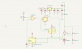
I have a lawnmower, DC motor control (motor is rated 28A 48V) of which is dead. So I decided to assemble a replacement DC motor control which worked perfectly fine for 5 minutes, start/stop and then MOSFET blew up in pieces, I believe it happened during startup of the motor. Variable resistor was set to 1.4V which corresponds to ~10A or ~11A, just did it to limit the current during testing. Idea behind was to measure the current and if exceed the threshold then shutdown the FET, otherwise open. Conenction from the OPAMP used as comparator to FET was done thru D trigger which was clocked at 1MHz to avoid uneccessary switching, see schematics. FET itself is rated 100V 180A so in theory should not be an issue but it is blown apart. What went wrong? I have my own ideas but I want to hear from people what might went wrong
 

Attachments

crutschow

Joined Mar 14, 2008
38,322
Likely the MOSFET needs 10V on the gate to fully turn it on, not 5V as you apparently are applying.
Check the voltage shown in the MOSFET data sheet where the on-resistance value is specified.

Is the MOSFET mounted on a heat-sink?
 

schmitt trigger

Joined Jul 12, 2010
2,027
The CMOS gate IS NOT, by a long shot, an adequate mosfet gate driver. Use one of the many ubiquitous IC drivers or at the very least use a PNP/NPN follower pair.
Also, as Cruts has already pointed out, why use 5 volts? Use 12 volts, and it will provide much better noise immunity.
 

Thread Starter

alxlabs

Joined Jan 12, 2023
12
Likely the MOSFET needs 10V on the gate to fully turn it on, not 5V as you apparently are applying.
Check the voltage shown in the MOSFET data sheet where the on-resistance value is specified.

Is the MOSFET mounted on a heat-sink?
Yes, heat sink is used
This is from MOFSET datasheet
VDS 100V
ID (at VGS = 10V) 140A
RDS(ON) (at VGS = 10V) < 7.5mΩ
RDS(ON) (at VGS = 4.5V) < 8mΩ

From this I cocnluded that at 5V it should be less than 8mΩ
 

schmitt trigger

Joined Jul 12, 2010
2,027
Lastly are you really using a 1 Mhz clock? You don’t require that high a frequency and all the parasitic elements will get you in trouble. Go way down in frequency, I say 20 Khz or so.
 

Thread Starter

alxlabs

Joined Jan 12, 2023
12
Lastly are you really using a 1 Mhz clock? You don’t require that high a frequency and all the parasitic elements will get you in trouble. Go way down in frequency, I say 20 Khz or so.
Yes, this is another idea I have, I actually bounced between using ~32KHz and even 500Hz but was thinking that 500Hz it is too low. Will re-try with 32KHz
 

Thread Starter

alxlabs

Joined Jan 12, 2023
12
Let me post here my findings and conclusion just for sake of those who will be dealing with the same problem

1. Hookup to the battery: I did not change what was done there by default in the original design, meaning to disconnect by the button only the ground while two connections for the power was used from 24V and 48V. When the issue occurred, FET got fried then shorted between gate and drain and then 48V killed practically everything in the schematics, but even worse, it fried thru the 5v regulator. When I released the start button, still the system was powered thru remaining 24V as power button really disconnect only one ov the voltages. All this lead to motor was partially powered even when power button was off - this is bad.

Conclusion - one does not need to follow the original schematics. Probably it was done to save couple of pennies as doing 24V->5V or 12V is cheaper than 48V->5V but I did not have to follow this concept as I don't care about price difference between regulators, so only one voltage have to be used, and it is 48V

2. Driving FET by 5V source: 5V is ok based on the datasheet, however logic gate output went badly sloppy when it reached 3V until 5V from 0 condition. From FET datasheet it seems that 4.5V is enough however the fact that it was going relatively slowly from 3V to 5V caused some extra resistance which transformed to the heat which killed the FET.

Cocnclusion: 10V for driving gate should be used and preferably thru opto device to avoid main board being fried if FET will get burnt. 10V will help even if there will be some slope between 5V and 10V - FET will be enough open anyways and this won't hurt

3. Just by looking at FET itself I had a concern about it's ability to handle high currents, may be it is better to use physically larger device, again it is not that bad price-wise and I don't need to save at every corner

4. The frequency I've chosen was because I had 1M oscillator. I don't know how much that contributed to an issue, but it would be wiser to use something like 20-30KHz and not 1MHz
 

dendad

Joined Feb 20, 2016
4,635
I don't like the power setup from the split battery and switched GND. The top battery would have a reverse voltage path via the 5V reg when the switch is off. That worries me. I see you will fix this. Good.
The 1N4007 across the motor is way too small in current rating, and totally not suitable tor high frequency switching.
Then there is the problem of FET gate capacitance. You do not have enough drive capability, and that is particularly so at such high frequency. 5V may be ok for the gate drive level, but it would have trouble getting there as the gate capacitance would not have time to charge and discharge when just driving from the low current source, so the FET will be running in a "linear" mode, not fully switching.
Have you put a scope on the gate to see the waveform?
A LM555 would work quite well in place of your 1Mhz osc.
 

Thread Starter

alxlabs

Joined Jan 12, 2023
12
I don't like the power setup from the split battery and switched GND. The top battery would have a reverse voltage path via the 5V reg when the switch is off. That worries me. I see you will fix this. Good.
The 1N4007 across the motor is way too small in current rating, and totally not suitable tor high frequency switching.
Then there is the problem of FET gate capacitance. You do not have enough drive capability, and that is particularly so at such high frequency. 5V may be ok for the gate drive level, but it would have trouble getting there as the gate capacitance would not have time to charge and discharge when just driving from the low current source, so the FET will be running in a "linear" mode, not fully switching.
Have you put a scope on the gate to see the waveform?
A LM555 would work quite well in place of your 1Mhz osc.
I saw on the scope that waveform on the gate is kind of weird between 3V and 5V, but I did not save it. That's why I think that even if 5V is OK for FET - it is still a bad idea to drive it from 5V logic. It should be driven from 10V so I think that some opto device has to be used between logic and FET, opto because if FET will be blown off in the scenario when gate gets shorted to drain - it won't burn rest of the schematics. I also think that middle connection to the batteries shall not be used. In my case it was simply done just because it was done that way originally while after the smokes went out I realized that what worked for cost savings is not neccesary best solution. Which proves that hardware runs on smokes - it won't work any longer once you let smoke out.
 

dendad

Joined Feb 20, 2016
4,635
it won't work any longer once you let smoke out.
Yes! All electronics works on smoke.
I saw on the scope that waveform on the gate is kind of weird between 3V and 5V,
The gate waveform needs to be as close to a rectangular waveform as you can get it, with good rise and fall times. If it is a saw tooth, then the FET is not being driven well and it will heat up as it is spending more time in the linear mode and not fully switched on or off. That is why FET drivers are good for high current, to charge and discharge the significant gate capacitance the FET has.
 
Top