 Facebook
 Google
 GitHub
 Linkedin
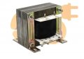
Hi, I have a 230V AC power supply at 50Hz. I also have a center-tapped transformer that steps down 230V to ±18V (i.e., +18V, 0V, -18V) with a current rating of 5 amperes. To power my electronics, I need DC outputs of +15V, -15V, +5V, +12V, and -12V. I wish to know
1) Which diode is best for a bridge rectifier?
I’m considering using the MBR20100 diode.
2) Should I use only a capacitor filter, or LC/CLC filters? What values should I choose? Simulations suggest larger values perform better.
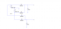
3) Can I connect LM7815, LM7805, LM7808, and LM7812 in parallel at the positive output (Point A in the circuit image)? Similarly, can I connect LM7915 and LM7912 in parallel at the negative output (Point B)?
4) Do I need to attach a heatsink to the transformer? Conceptually, does the transformer only draw power when the electronic circuit is consuming current (i.e., when the regulators output power), or is it always active and generating heat even when idle?
5) Since I need more DC power from the positive rail than the negative rail, does that mean I need to dissipate more heat on the negative side, or just on the side where more power is used?
1) Which diode is best for a bridge rectifier?
I’m considering using the MBR20100 diode.
2) Should I use only a capacitor filter, or LC/CLC filters? What values should I choose? Simulations suggest larger values perform better.
3) Can I connect LM7815, LM7805, LM7808, and LM7812 in parallel at the positive output (Point A in the circuit image)? Similarly, can I connect LM7915 and LM7912 in parallel at the negative output (Point B)?
4) Do I need to attach a heatsink to the transformer? Conceptually, does the transformer only draw power when the electronic circuit is consuming current (i.e., when the regulators output power), or is it always active and generating heat even when idle?
5) Since I need more DC power from the positive rail than the negative rail, does that mean I need to dissipate more heat on the negative side, or just on the side where more power is used?
Attachments
-
 32 KB Views: 5
 -
 14.2 KB Views: 6
 -
249.7 KB Views: 1


