 Facebook
 Google
 GitHub
 Linkedin
Hi all
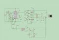
I designed 20A charger using tl494 ,the problem mosfet damaged many time one I connect mains rectified DC volt, also IC damaged,
I tried circuit without feedback many time so duty cycle 45% without any problem, I think when duty cycle close to 0 , mosfet bomb ,I think I need some component for protection
Attachments
-
 78.5 KB Views: 66


